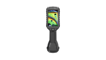
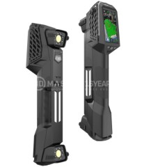
When researching a 3D scanner, many businesses focus only on the price or accuracy while overlooking other critical technical specifications. In reality, every specification reflects the scanner's performance in different applications. Understanding these specifications helps businesses choose the right 3D scanning machine, optimize investment costs, and maximize equipment efficiency.
Technical specifications are more than just product information—they are the foundation for evaluating whether a 3D scanner can meet specific application requirements.
Without carefully reviewing the specifications, businesses can easily invest in the wrong equipment. Therefore, companies should evaluate the following technical parameters before making a purchase:
.jpg)
Accuracy represents the deviation between the scanned data and the actual dimensions of the object. It is the most critical specification for quality inspection, metrology, and reverse engineering applications.
Industrial 3D scanners typically offer accuracy ranging from 0.015–0.05 mm, while entry-level models usually provide 0.05–0.1 mm or higher depending on the technology and measurement conditions.
For example, the FARO Creaform HandySCAN EVO Plus delivers 0.020 mm accuracy, meaning the maximum measurement error is only about 20 microns per measurement point. This makes it ideal for industries requiring extremely high precision, such as automotive, aerospace, precision machining, and mold manufacturing.
Note: A smaller accuracy value indicates higher measurement precision. However, not every application requires ultra-high accuracy.
Resolution refers to the minimum distance between two data points that the scanner can still recognize as separate features.
This specification determines how well the scanner can reproduce fine details such as grooves, engraved text, embossed characters, textures, and intricate surface features. Higher resolution results in sharper and more detailed 3D models.
Typical resolution ranges include:
It is important to distinguish accuracy from resolution. Accuracy determines dimensional measurement error, while resolution determines the level of detail captured in the scanned data.
Scan speed indicates the amount of data a 3D scanner can capture per second and is usually expressed in points per second or million points per second.
Many modern industrial scanners can capture between 1.3 million and nearly 3.8 million points per second, significantly reducing the time required to scan large components.
Higher scan speeds shorten measurement time, improve productivity, and reduce the risk of data loss during scanning.
.jpg)
The number of laser lines refers to how many laser beams are projected simultaneously during 3D data acquisition. Each laser line scans a different section of the object's surface, allowing more data points to be collected with each movement.
For example, industrial scanners such as the FARO Creaform HandySCAN EVO Elite feature 46 laser lines plus one additional laser line, combined with wireless connectivity to maximize flexibility and productivity in demanding industrial environments.
However, more laser lines do not necessarily mean higher accuracy. Accuracy primarily depends on the sensor, processing algorithms, and calibration, while additional laser lines mainly improve scanning speed and data collection efficiency.
In addition to multiple laser modes, many 3D scanners also support Single Laser Mode.
This mode is particularly useful for:
As a result, the collected data becomes more complete, reducing missing scan points and improving the accuracy of the final 3D model.
Field of View (FOV) is the size of the area that the scanner captures in a single scan. It is typically expressed in mm × mm or mm².
Industrial 3D scanners usually offer an FOV ranging from 50 × 50 mm for small components to approximately 1000 × 1000 mm for large objects.
Choosing the appropriate FOV requires balancing scanning speed and model detail. A larger FOV scans faster but captures less detail, while a smaller FOV delivers finer detail but requires more scanning passes.
Working Distance is the optimal distance between the scanner head and the object's surface, where the laser or structured light sensor achieves the highest measurement accuracy specified by the manufacturer.
Each 3D scanner model has its own recommended working distance. Typical ranges include:
Positioning the scanner too close reduces the Field of View and may result in incomplete data capture. Holding it too far away weakens the signal, increases noise, and can increase measurement errors from 0.02 mm to 0.1–0.3 mm, depending on the device.
Modern 3D scanners are often equipped with automatic focus balancing or real-time distance indicators, helping operators maintain the correct working distance throughout the scanning process to ensure consistent accuracy and stable data quality.
.jpg)
A scanner's operating mode defines how it functions during the scanning process and determines its flexibility across different environments and applications.
Today, most 3D scanners support several common operating modes, including:
Selecting the appropriate operating mode helps optimize scanning efficiency for different applications, improves data stability during measurement, and increases flexibility when scanning objects of various shapes and sizes.
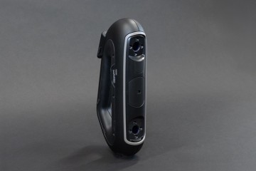
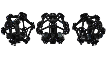
Tracking Mode refers to the method a 3D scanner uses to determine the position of the scanner head throughout the scanning process.
Common tracking methods include:
Reliable tracking minimizes signal loss and ensures continuous, seamless data acquisition throughout the scanning process.
|
Application |
Accuracy |
Resolution |
Scan Speed |
Priority Features |
|
Quality Inspection |
Very High (≤ 0.025 mm) |
High (0.020–0.050 mm) |
Medium to High |
High repeatability, ISO certification |
|
Reverse Engineering |
High (0.030–0.050 mm) |
Medium (0.050–0.100 mm) |
Fast |
Narrow-area scanning mode, CAD software compatibility |
|
Heritage Digitization & Large Mold Scanning |
Medium (≥ 0.050 mm) |
Standard |
Very Fast |
Large FOV, multiple laser lines |
|
Small Parts & Jewelry Scanning |
Extremely High |
Ultra-fine (≤ 0.020 mm) |
Standard |
Single Laser Mode, ultra-high resolution |
Every business has different inspection and 3D digitization requirements. Therefore, before investing in a 3D scanner, it is essential to clearly identify your actual needs to select the most suitable equipment.
In summary, businesses should evaluate factors such as accuracy, resolution, scan speed, Field of View, tracking method, data processing capability, and intended application to invest in the right 3D scanner and maximize long-term efficiency.
3D MASTER is proud to be the official distributor of FARO Creaform 3D scanning technology in Vietnam for more than 10 years, providing professional consultation, live demonstrations, and comprehensive 3D scanning and industrial metrology solutions tailored to your business needs.
Contact Information – 3D MASTER
Hotline / Zalo / LINE / Telegram / WhatsApp / Viber / KakaoTalk:
+84 982 089 198 | +84 986 333 960
Email:
cuong3dmaster@gmail.com
hung3dmaster@gmail.com
tech3dmaster@gmail.com
Website:
https://3dmaster.com.vn