Recreate Excavator Bucket Drawings in Just a Few Minutes Using 3D Scanning Technology at 3D Master
Recreate Excavator Bucket Drawings in Just a Few Minutes Using 3D Scanning Technology at 3D Master
Posted Date: 08-08-2026
Recreate Excavator Bucket Drawings in Just a Few Minutes Using 3D Scanning Technology at 3D Master
Excavator bucket drawings are an important foundation for repair, manufacturing, and precision machining. However, many businesses no longer retain the original drawings or only have physical buckets that have become worn and deformed after prolonged use, making it difficult and costly to measure and recreate drawings using traditional methods. With the support of 3D scanning technology combined with reverse engineering, businesses can quickly restore accurate CAD models and technical drawings, shorten design time, and optimize repair and manufacturing processes.
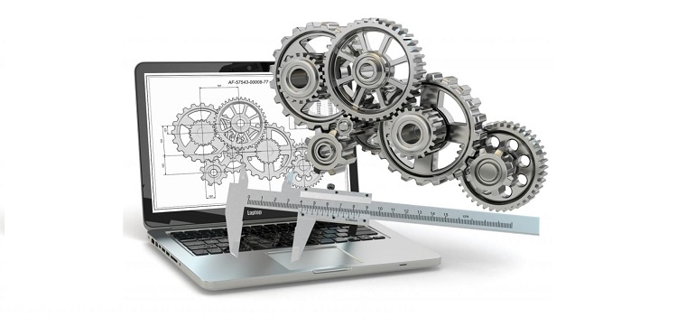
3D scanning helps quickly create excavator bucket drawings from physical parts for repair and manufacturing.
1. Challenges of Creating Excavator Bucket Drawings Using Traditional Methods
An excavator bucket is a complex welded mechanical component consisting of multiple curved surfaces, reinforcing ribs, bucket ears, pin holes, and wear-resistant cutting edges.
Therefore, recreating an excavator bucket drawing using traditional measurement methods not only requires significant manpower but also carries a high risk of measurement errors.
Complex manual measurement: Requires multiple types of measuring tools to capture individual dimensions, especially for curved and asymmetrical surfaces.
Time- and labor-intensive: Measuring hundreds of dimensions, cross-checking measurements, and rebuilding the CAD model can take anywhere from several hours to several days.
High risk of errors: Even a few inaccurate measurements can cause deviations in bucket pin hole positions, mounting angles, and other critical dimensions, directly affecting machining and assembly.
Manual measurement only reflects the current condition: It is difficult to determine the original design geometry for accurate restoration.
Difficult to modify, store, share, or reuse for future repair and manufacturing projects.
In particular, errors during measurement or drawing reconstruction can result in incorrect machining dimensions, repeated modifications, increased material and labor costs, and extended project schedules.
Excavator buckets are complex welded mechanical components that are difficult to measure manually
2. Solution: Outstanding Benefits of 3D Scanning Technology for Fast and Accurate Drawing Creation
The emergence of 3D scanning technology has revolutionized the process of recreating construction machinery components. By projecting millions of laser points onto the bucket surface, a 3D scanner captures the complete geometric shape of the bucket and converts it into digital data on a computer.
This breakthrough solution enables excavator bucket drawings to be created with a wide range of outstanding advantages:
Extremely fast: On-site 3D scanning takes only 30–60 minutes. CAD modeling and complete drawing generation can be completed within 1–2 days, saving up to 80% of the time compared with manual measurement.
High accuracy: Extremely low measurement error (0.015 mm–0.075 mm), ensuring critical features such as bucket pin centers, mounting walls, and mating surfaces are accurately reproduced.
Restoring the original worn geometry: Reverse engineering software automatically processes wear, compensates for chipped or missing steel sections, and corrects deformation to reconstruct the manufacturer's standard dimensions.
Optimization & reinforcement: Reinforcing ribs can be easily added and critical load-bearing areas can be thickened to extend the bucket's service life by 1.5–2 times.
Digitization & storage: Excavator bucket CAD/CAM drawing files can be stored permanently on a computer and are ready for CNC cutting whenever reproduction is required, eliminating the need for repeated measurements.
3. How Does 3D Scanning Help Restore Excavator Bucket Drawings?
3D scanning digitizes the entire geometry of an excavator bucket into highly accurate 3D data through the following basic steps:
Step 1: 3D Scanning to Capture Excavator Bucket Surface Data
Engineers use a 3D scanner to scan the entire bucket surface, capturing millions of data points (Point Cloud) covering components such as the bucket body, cutting edge, bucket ears, pin holes, reinforcing ribs, and complex curved surfaces.
This process accurately records the actual geometry without requiring every dimension to be measured manually.
Step 2: Process Scan Data and Create a Mesh Model
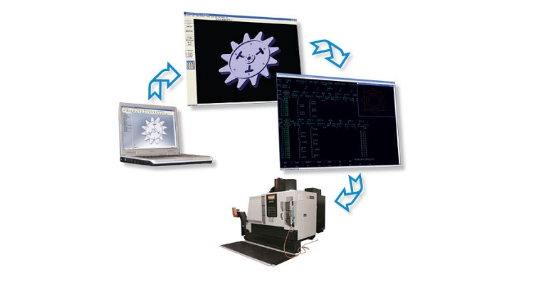
After acquisition, Point Cloud data is processed to remove noise, align scans, and merge scanned areas. The result is a 3D Mesh model in common formats such as STL or OBJ, fully representing the geometry of the excavator bucket.
Step 3: Reverse Engineering to Create the CAD Model
Based on the Mesh model, engineers perform reverse engineering to recreate a parametric CAD model. This is a critical step in restoring the bucket's original design geometry while allowing worn or deformed areas to be corrected and modifications to be incorporated according to production requirements.
Step 4: Export Excavator Bucket Drawings for Manufacturing
Once the CAD model is completed, the system exports excavator bucket drawings as 2D technical drawings or 3D models in formats such as DWG, DXF, PDF, STEP, IGES, and more.
These data can be used directly for CNC machining, laser cutting, plasma cutting, welding repair, manufacturing new buckets, or long-term storage for future projects.
4. What Types of Excavator Buckets Are Suitable for 3D Scanning?
One of the key advantages of 3D scanning technology is its ability to accurately digitize most types of excavator buckets, from standard models to buckets with complex structures or large dimensions.
Digging buckets: The most common type used on Komatsu, Kobelco, Caterpillar, and Hitachi excavators. Accurate drawings are required for bucket opening dimensions and digging clearance angles.
Rock buckets: Buckets with thick reinforcing ribs and complex load-bearing plates. 3D scanning helps accurately calculate the profiles of steel plates designed to withstand impact.
Tilting buckets: Buckets equipped with hydraulic cylinders that provide flexible tilting movement, requiring highly accurate 3D drawings of the pivot joints and cylinder mounting points.
Mini excavator buckets: Small in size but containing numerous detailed components. 3D scanning can capture their geometry and generate drawings in as little as 15 minutes.
Clamshell excavator buckets: Consist of multiple bucket shells that open and close using a hydraulic system. 3D scanning helps ensure accurate alignment and tight engagement between the bucket halves.
Skeleton / screening buckets: Feature steel bars arranged in a grid for screening and separating rock or soil. 3D scanning quickly extracts the positions and spacing of the individual bars.
Breaker / slag buckets: Specialized designs engineered to withstand extremely high impact loads, requiring 3D scanning for simulation and reinforcement structure upgrades.
Sand / cleanup buckets: Large-capacity buckets with wide interiors. 3D scanning helps optimize the amount of steel material used to reduce the load on the excavator boom and arm.
Wheeled excavator buckets: Highly flexible bucket designs compatible with wheeled excavators, requiring precise mounting pin dimensions for easy load and attachment changes.
Crawler excavator buckets: Buckets ranging from mini excavator models to ultra-large heavy-duty buckets used in ore, coal, and granite mining operations.
Whether the bucket is new, used, worn, or no longer has technical documentation, 3D scanning combined with reverse engineering can restore design data with high accuracy, allowing businesses to quickly obtain excavator bucket drawings and CAD models for repair, machining, or customized manufacturing.
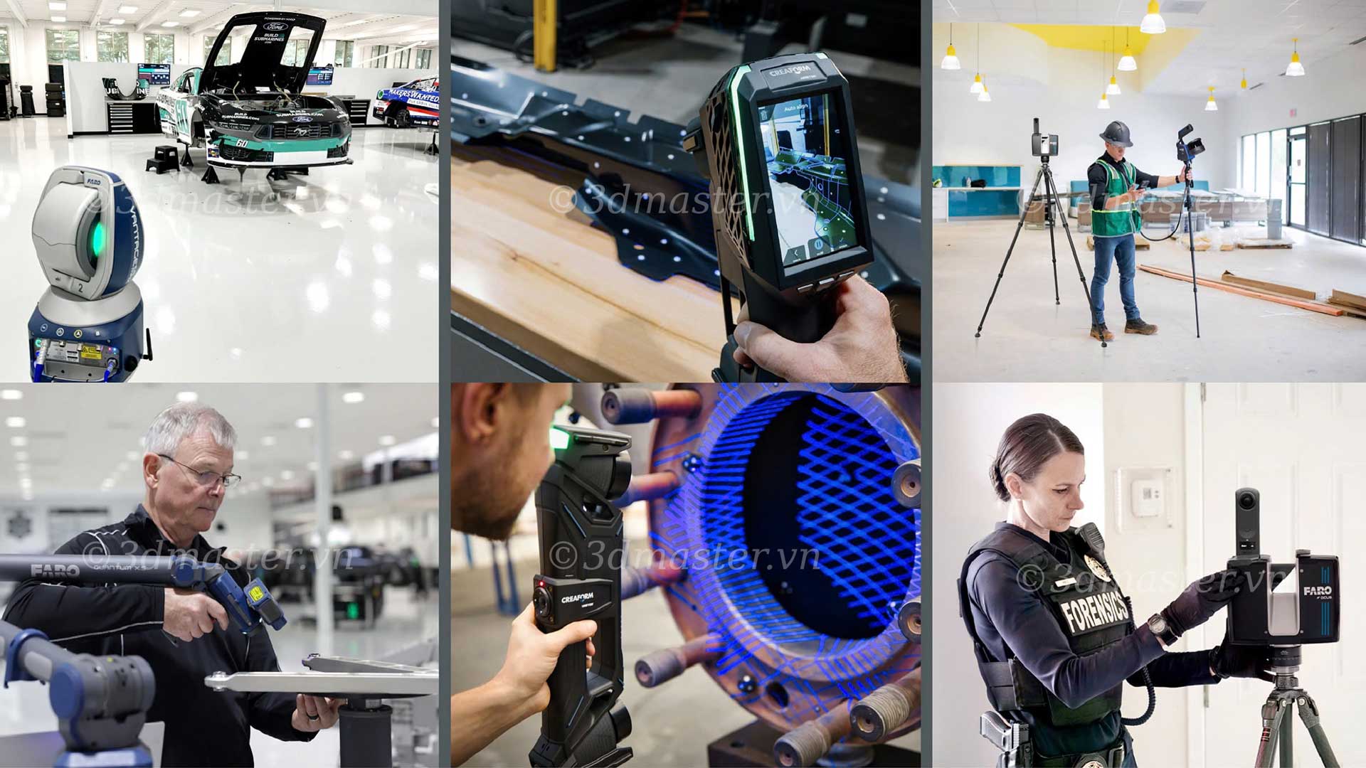
Engineers use a 3D scanner to capture the geometric data of an excavator bucket
5. Professional 3D Scanning Services for Fast Excavator Bucket Drawing Creation
With many years of experience in 3D measurement and digitization, 3D Master provides professional excavator bucket 3D scanning services, helping businesses quickly build CAD models and technical drawings for repair, machining, and manufacturing.
Practical experience: Hundreds of 3D digitization projects have been implemented for construction machinery, excavator buckets, and heavy-duty mechanical components for major companies and corporations.
Advanced measurement equipment: Equipped with genuine Faro Creaform portable laser 3D scanners for accurate scanning directly at machinery yards or construction sites.
Mechanical engineering expertise: An experienced engineering team with strong knowledge of machining tolerances, welding technology, sheet metal bending, and excavator bucket load principles.
Comprehensive data delivery: Provides complete 3D CAD files (STEP, IGES), 2D CNC drawings (DWG, DXF), and original mesh files (STL).
Comprehensive technical support: Provides consultation on reinforcement improvements, excavator bucket pin tolerances, and on-site scanning services according to customer requirements.
6. FAQs - Frequently Asked Questions
- Can 3D scanning immediately generate an excavator bucket drawing?
No. 3D scanning data must be processed through reverse engineering to create a complete CAD model and excavator bucket drawing.
- Can a worn excavator bucket be 3D scanned?
Yes. 3D scanning can still capture the current condition of the bucket. Engineers can then restore or modify the geometry according to the required specifications.
- How long does 3D scanning and drawing delivery take?
On-site scanning at the machinery yard takes 30–60 minutes. CAD modeling and completion of 2D/3D manufacturing drawings take approximately 24–48 hours.
- Can the exported files be used directly with CNC cutting machines?
Yes. Standard 1:1 scale .DXF/.DWG files can be delivered and loaded directly into Laser/Plasma CNC cutting machines for immediate steel plate cutting.
- Does the bucket need to be transported to the workshop for scanning?
No. Laser 3D scanning equipment is compact and lightweight, allowing engineers to visit the customer's construction site, machinery yard, or workshop to perform on-site scanning.
- Is 3D scanning more expensive than manual measurement?
The cost is highly reasonable. Considering overall efficiency, 3D scanning can provide significant savings by eliminating the risk of incorrect steel blanks and minimizing machine downtime.
- Does 3D Master sign confidentiality agreements for customers' design data?
Yes. All 3D scanning data, CAD models, and technical drawings are kept confidential according to customer requirements, ensuring information security throughout the project.
In today's competitive environment, where cost optimization is increasingly important, proactively digitizing construction machinery components is a strategic step for businesses. 3D scanning technology not only effectively solves the problem of missing excavator bucket drawings but also elevates repair and manufacturing processes, making them faster, more accurate, and more professional than ever before.
>>> Need an Excavator Bucket Drawing Fast? - Get a 3D Scan Quickly, On-Site!
Dùng máy scan 3D đo thì chuẩn khỏi bàn rồi. Nhưng với gầu bị biến dạng móp méo nặng thì bên mình xử lý nắn lại phom chuẩn NSX trên phần mềm mất bao lâu vậy admin?
.png)
.jpg)

.jpg)