How Are Vietnamese Humanoid Robots Manufactured Using 3D Technology?
How Are Vietnamese Humanoid Robots Manufactured Using 3D Technology?
Posted Date: 10-09-2026
How Are Vietnamese Humanoid Robots Manufactured Using 3D Technology?
The biggest barrier to commercializing Vietnamese humanoid robots is not the idea itself, but the high cost of molds and the lengthy R&D iteration cycles. The combination of 3D Scanning – 3D Printing and reverse engineering provides a strategic “shortcut,” helping reduce dependence on foreign components, shorten testing time by 70%, and optimize production costs from the prototyping stage.
What Role Does 3D Technology Play in the Manufacturing Process of Vietnamese Humanoid Robots?
For humanoid robots, even a small change in dimensions, shape, or mounting position can affect movement, weight, and the coordination between components.
Therefore, instead of relying solely on traditional measurement and manufacturing methods, the development process can utilize 3D data throughout the entire workflow, from design to inspection.
The combination of 3D Scanning and 3D Printing is a powerful tool and a core foundation for reshaping the R&D capabilities of the domestic robotics industry, particularly for intelligent humanoid robots:
Optimize 60–70% of R&D costs: Eliminate the need for expensive trial casting molds and enable components to be produced directly from CAD files.
3D scanning for accuracy inspection: Digitize and compare actual components with design files to immediately detect mechanical tolerances or deformation.
3D printing for rapid prototyping: Test shapes, housing structures, and moving joints within hours instead of several weeks.
Take control of the supply chain: Manufacture unique components locally, significantly reducing dependence on expensive imported parts.
Shorten the improvement cycle: 3D Design → Prototyping → 3D Inspection → Analysis → Improvement → New Prototype
The faster the R&D iteration cycle, the easier it is for businesses to test multiple solutions and bring robots to market sooner.
3D technology helps shorten the design, prototyping, and improvement process for humanoid robots
2. How Does the 3D Technology and Reverse Engineering Process Help Reduce Humanoid Robot Manufacturing Time by 70%?
Applying a standardized workflow from digitization to physical manufacturing can reduce a single improvement cycle from several months to just a few days:
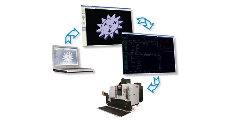
Robot/Existing Component → 3D Scanning → Data Processing → CAD Reverse Engineering → Design Optimization → 3D Printing for Prototyping → Assembly & Testing → 3D Inspection → Finalization
Step 1: 3D Scan Existing Robot Components or Assemblies
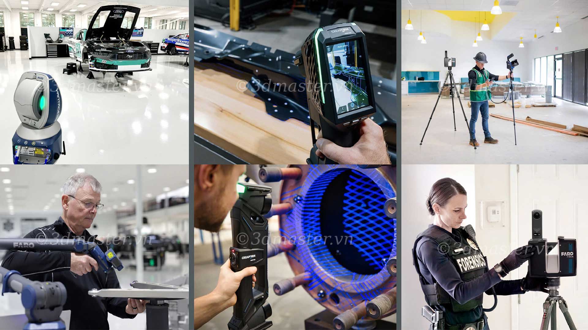
First, engineers identify the component that needs to be digitized and select an appropriate scanner, such as Faro Creaform HandySCAN / MetraSCAN, based on its size, material, complexity, and required accuracy.
The process includes:
Cleaning and preparing the component before scanning.
Applying markers or setting up an appropriate tracking method when necessary.
Scanning the entire geometric area that needs to be captured.
Taking additional scans of hidden or obstructed areas.
Collecting complete point cloud/mesh data.
For robot components with complex shapes, 3D Scanning enables engineers to directly capture the product's geometry instead of manually measuring each individual location.
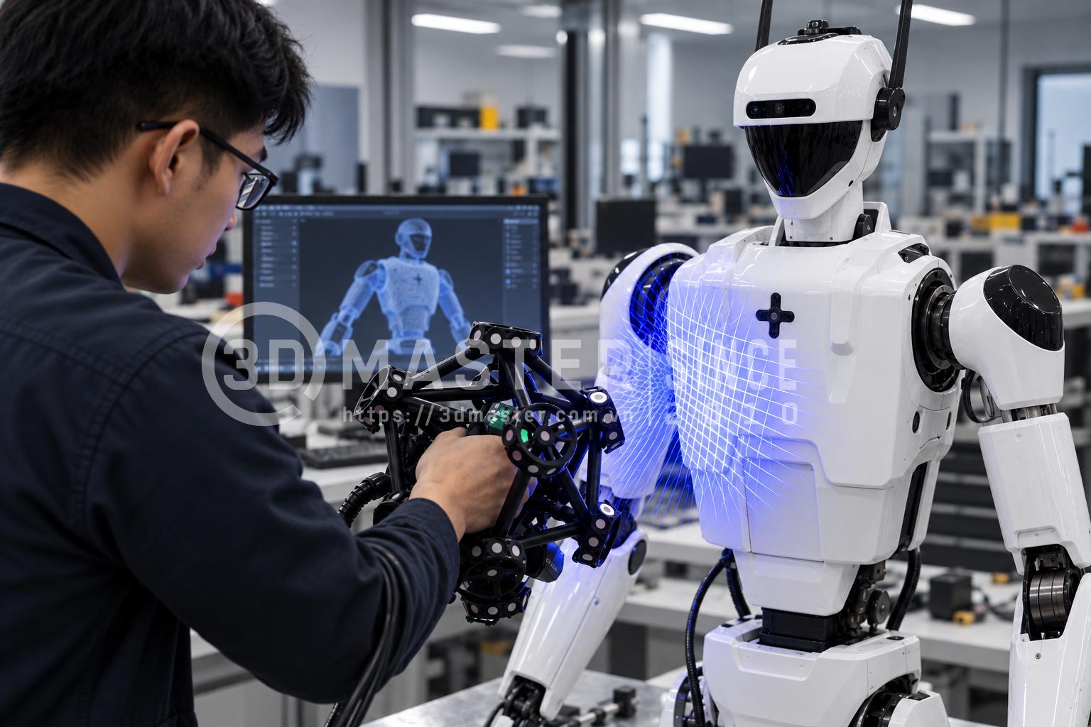
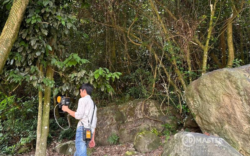
Engineers use a 3D scanner to digitize components on a humanoid robot
Step 2: Process the Scanned Data
3D scan data cannot be immediately used for design. Engineers need to import the scanned data into specialized software such as VXmodel or PolyWorks:
Remove noise and unnecessary data.
Merge scanned areas into a unified model.
Align different areas of the data.
Repair holes or missing data regions.
Create a mesh suitable for the intended application.
The result is a digital 3D model that accurately represents the geometry of the actual component.
Step 3: Reverse Engineering and Rebuilding the CAD Model
This is the step where scan data is transformed into an editable model. Engineers use specialized reverse engineering software to convert 3D mesh data into a parametric CAD model:
Identify planes, axes, centerlines, and geometric features.
Recognize flat and curved surfaces, holes, grooves, and mounting locations.
Reconstruct each required geometric feature of the component.
Build an editable CAD model for design and manufacturing.
Check the level of conformity between the CAD model and 3D scan data.
Step 4: Analyze and Optimize the Design
Once the CAD model has been created, engineers can continue to:
Adjust dimensions.
Modify the structure or design according to requirements.
Optimize assembly positions.
Add mounting locations for sensors, cameras, or other components.
Adjust the design according to weight and operating requirements.
Evaluate compatibility when integrating with related components.
This is a key advantage of reverse engineering: it does not simply reproduce an existing component but also creates a foundation for developing an improved version.
Step 5: 3D Printing to Create a Robot Prototype or New Component
After the CAD model has been finalized, engineers can transfer it to a 3D printing process to create a prototype.
The printed prototype can be used to:
Check the overall shape.
Verify dimensions.
Test assembly.
Check the available space for components.
Evaluate movement.
Create and validate multiple design options.
For components that do not yet need to be manufactured from the final production material, 3D printing is particularly suitable for validating the design before moving to machining or full-scale production.
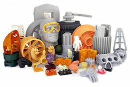
3D printing enables engineers to quickly create and test humanoid robot components.
Step 6: Assembly, Testing, and Continuous Improvement
The new prototype is integrated into the robot assembly for real-world testing:
Fit between components.
Clearances during movement.
Component mounting capability.
Structural stability.
Areas requiring modification after testing.
If an issue is identified, engineers return to the CAD model, make adjustments, and create a new version. This is the R&D iteration cycle for robotics.
Step 7: 3D Scan to Inspect the Manufactured Version and Move into Production
Once the component reaches the desired design version, 3D scanning can be used to inspect the actual product:
CAD Design ↔ Actual 3D Scan Data
This allows engineers to determine:
Whether the actual dimensions meet the required specifications.
Which areas contain deviations.
Whether the deviation is within the acceptable tolerance range.
Whether the manufacturing process needs to be adjusted.
Once the component meets the requirements, the data can be used as a basis for the production stage.
Applications of 3D Technology in Humanoid Robot Manufacturing
3D technology is not limited to the robot's “outer shell.” It can be applied to numerous components that require complex geometries, rapid prototyping, or continuous optimization.
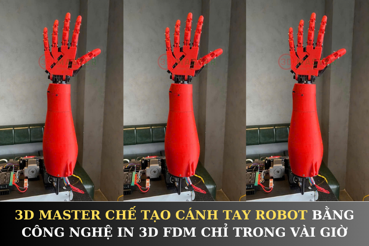
Manufacturing robot hands and arms: 3D scanning accurately captures the shape of individual components. The data can be used for reverse engineering and 3D printing prototypes to optimize movement.
Creating robot housings: 3D scanning helps capture geometric data and reverse engineer complex surfaces. The resulting models can then be 3D printed to test the appearance before production.
Creating mounts for cameras and sensors: 3D scanning accurately determines the available space and mounting positions, allowing engineers to create precise mounting designs and rapidly 3D print prototypes.
Recreating components without drawings: 3D scanning digitizes the actual component, which can then be reverse engineered into a CAD model for modification, improvement, or remanufacturing.
Inspecting components after manufacturing: 3D scanning captures the finished product and compares it with the CAD model, helping detect deviations in dimensions, shape, and assembly positions.
Improving through multiple iterations: 3D scan data from an existing version helps engineers identify areas for improvement, design a new version, and quickly create a prototype using 3D printing.
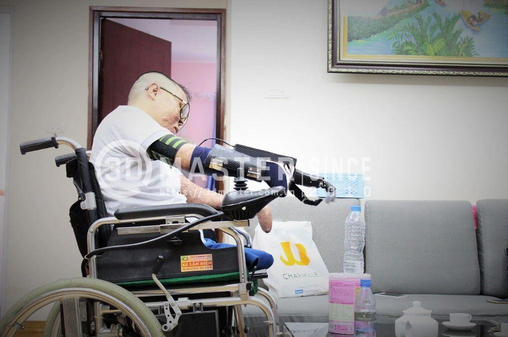
A pilot injured in an accident and robotic hands capable of grasping, manufactured by 3D Master
3D Master Provides Professional 3D Technology Services to Support Vietnamese Humanoid Robot Manufacturing
As a pioneer in 3D digitization and prototyping solutions in Vietnam, 3D Master provides a comprehensive ecosystem that helps engineers and businesses develop humanoid robots while optimizing both time and costs.
Advanced equipment: Equipped with leading industrial handheld laser 3D scanners from Faro Creaform, enabling detailed robot components to be captured with metrology-level accuracy.
Diverse 3D printing technologies and large-format systems: Providing comprehensive solutions, from industrial plastic 3D printing for large components to high-strength SLM metal 3D printing.
Experienced engineering team: Supporting the processing of complex scan data and converting it into accurate CAD files, ready for simulation analysis and machining.
3D quality control services: Providing solutions for comparing manufactured models with CAD drawings and generating detailed GD&T inspection reports to ensure precise fits between robot components.
3D Master is committed to supporting Vietnamese robotics startups and research laboratories throughout the entire process, from initial concepts, scanning and material consultation to final product 3D printing.
In summary, 3D technology is becoming a valuable tool for developing Vietnamese humanoid robots faster and more accurately. From 3D Scanning and reverse engineering to 3D printing, engineers can shorten the prototyping, inspection, and improvement processes, creating a foundation for transforming robots from concepts into real-world products.