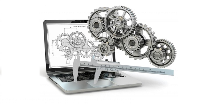
During mechanical manufacturing and upgrades, optimizing the single-stage gearbox drawing plays a decisive role in assembly accuracy and the transmission efficiency of the entire system. Whether you are working with conventional designs such as a single-stage straight spur gear reducer, more complex configurations such as a single-stage helical spur gear reducer drawing, or even a two-stage gearbox drawing, changes in available space and mounting dimensions always present engineers with challenging problems. This article explains in detail how 3D scanning technology can address these challenges quickly and efficiently.
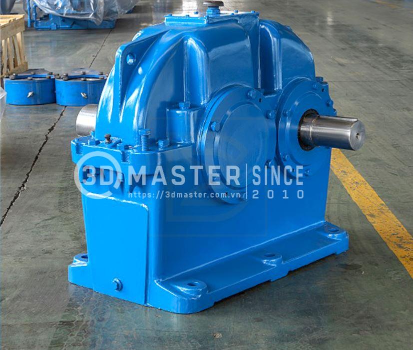
A single-stage gearbox is a mechanical transmission mechanism that uses one pair of meshing gears or a worm and worm wheel to reduce rotational speed and increase torque from the motor to the driven machine.
During operation, businesses may need to change mounting dimensions to accommodate a new production line, a different machine base, or a replacement motor.
In such cases, revisions to the single-stage gearbox assembly drawing must be based on the equipment's actual geometry, with a clear determination of which dimensions can be modified.
Common scenarios include:
Drawings no longer match the actual equipment: Dimensional discrepancies may result from years of machining and operation, wear, or replacement components that do not match the original archived documentation.
The new machine base differs from the original design: The center-to-center distances between mounting holes, anchor bolt positions, or input/output shaft heights may change to meet the structural requirements of the new production line.
Limited installation space: The gearbox may interfere with the machine frame, motor, coupling, or adjacent components.
Changes to one location may affect another: When the motor or transmission configuration changes, the flange, input shaft position, and connecting components may also require adjustments.
Instead of manufacturing an entirely new unit, businesses can consider modifying the mounting interfaces to meet the new requirements, provided that structural integrity and load-bearing capacity remain adequate.
NO. It is not always necessary to recreate the entire drawing. If the revision only affects specific areas, such as the mounting base, bolt holes, or flange, engineers can focus on these locations while retaining the components that have already been verified as suitable.
This approach reduces modeling workload and minimizes the risk of introducing dimensional discrepancies when redesigning components that do not require modification.
| Component Group | Recommended Approach to Revisions |
|---|---|
| Mounting base and bolt holes | Consider adjustments to fit the new machine base; check edge distances, strength, and load-bearing capacity after modification. |
| Flanges and connecting surfaces | Verify compatibility with the motor, coupling, and mating components to ensure proper assembly. |
| Gearbox housing and bearing covers | Check installation clearance, mating interfaces, and accessibility for disassembly and maintenance. |
| Input and output shafts | Retain the existing design unless changes are required. If modifications are necessary, check concentricity, connections, and load-bearing capacity. |
| Gears and center distance | Do not modify arbitrarily, as these parameters affect the transmission ratio, meshing conditions, and load-bearing capacity. |
Compared with measuring each location manually, 3D scanning captures geometric data from multiple surfaces simultaneously. Engineers can use the data to create a 3D model, identify the exact areas requiring modification, and avoid redrawing the entire assembly.
=
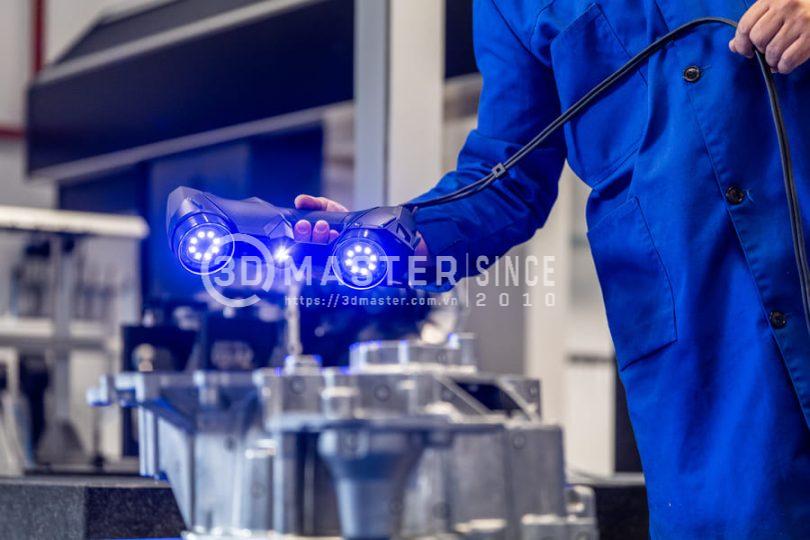
3D scanning technology uses lasers or light to capture the surface coordinates of an object, generating 3D data that represents its actual geometry. This data supports CAD modeling, drawing comparisons, and the identification of areas requiring modification.
Before making any modifications, engineers need to determine the gearbox's actual shape and dimensions. This is particularly important for equipment that has been in service or undergone repairs.
Digitize relevant surfaces: Scan the gearbox housing, mounting base, flanges, bearing covers, and other external areas related to installation.
Compare against existing drawings: Compare the scan data with the existing model or drawings to identify differences in geometry and component positioning.
Identify areas requiring additional measurements: Bearing mounting bores, shaft diameters, precision mating surfaces, and concealed features may require specialized measuring equipment or inspection after disassembly.
3D scanning data helps engineers better understand the equipment's actual geometry. However, scanning alone cannot determine the original dimensions if components have worn or deformed. These areas must be assessed using drawings, design specifications, measurements, and engineering evaluation.
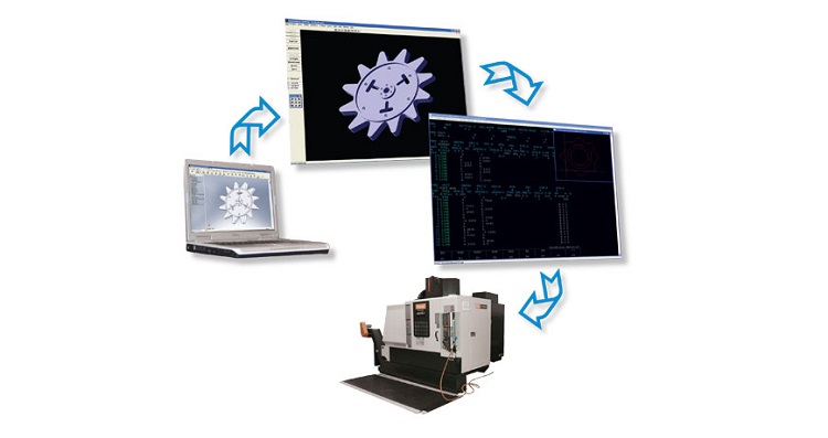
After processing the 3D scan data, engineers can develop a suitable CAD model to verify the installation positions and spatial relationships between the gearbox and related components.
Create a model based on actual geometry: Reconstruct the surfaces, holes, datum features, and other characteristics required for the revision.
Check compatibility with the new machine base: Verify mounting base positions, bolt-hole spacing, and installation height against the specified requirements.
Evaluate clearances: Check for potential interference with the motor, coupling, machine frame, and surrounding components.
Verify connection interfaces: Ensure that the revised configuration does not compromise critical geometric relationships within the transmission system.
Model-based verification helps identify layout problems before components are manufactured or remachined. The reliability of the results depends on scan data quality, model accuracy, and the completeness of the related component geometry.

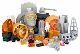

Once the areas requiring modification have been identified, engineers can adjust the CAD model and update the technical drawings to meet the new installation requirements.
Modify the mounting base and bolt holes: Change hole positions or spacing to match the machine base, while checking edge distances and load-bearing capacity.
Update flanges or connection positions: Modify these interfaces when installation requirements change, while verifying concentricity and connection compatibility.
Retain unaffected components: Components that have been verified as suitable can remain unchanged, reducing the overall design workload.
Finalize the revised drawings: Update the orthographic views, sectional views, dimensions, tolerances, and technical requirements necessary for machining and assembly.
If the proposed changes affect shafts, gears, center distance, or rolling bearings, engineers must reassess the relevant parameters. Geometric adjustments in a model should never be made without evaluating their impact on structural strength and transmission performance.
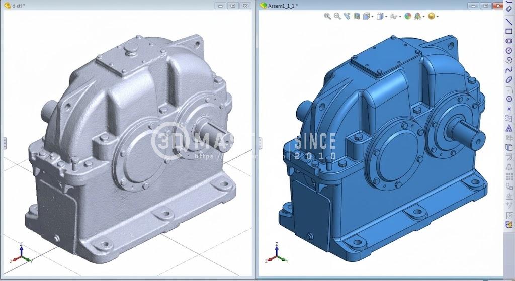
3D scanning is suitable when geometric data must be collected from multiple surfaces or when a model needs to be reconstructed from existing equipment. However, this method is not necessary in every situation.
Use 3D scanning: When the gearbox housing has complex geometry, the existing drawings lack sufficient information, or the entire assembly needs to be checked against a new installation space.
Manual measurement may be sufficient: When only a few simple, accessible dimensions need to be changed and reconstructing the overall geometry is unnecessary.
Combine scanning with dimensional inspection: When the general shape must be reconstructed while also verifying dimensions with tight tolerances, such as shaft diameters, bearing bores, and functional mating surfaces.
For reconstructing a single-stage gearbox drawing, a suitable approach is often to combine 3D scanning, mechanical dimensional inspection, and CAD software. This method enables faster collection of overall geometric data while maintaining control over critical assembly and transmission parameters.
To implement mechanical design improvements quickly, accurately, and cost-effectively, partnering with an experienced service provider is essential.
3D Master is proud to provide advanced industrial optical metrology and 3D scanning solutions, helping mechanical engineering businesses improve their confidence in the revision process through the following capabilities:
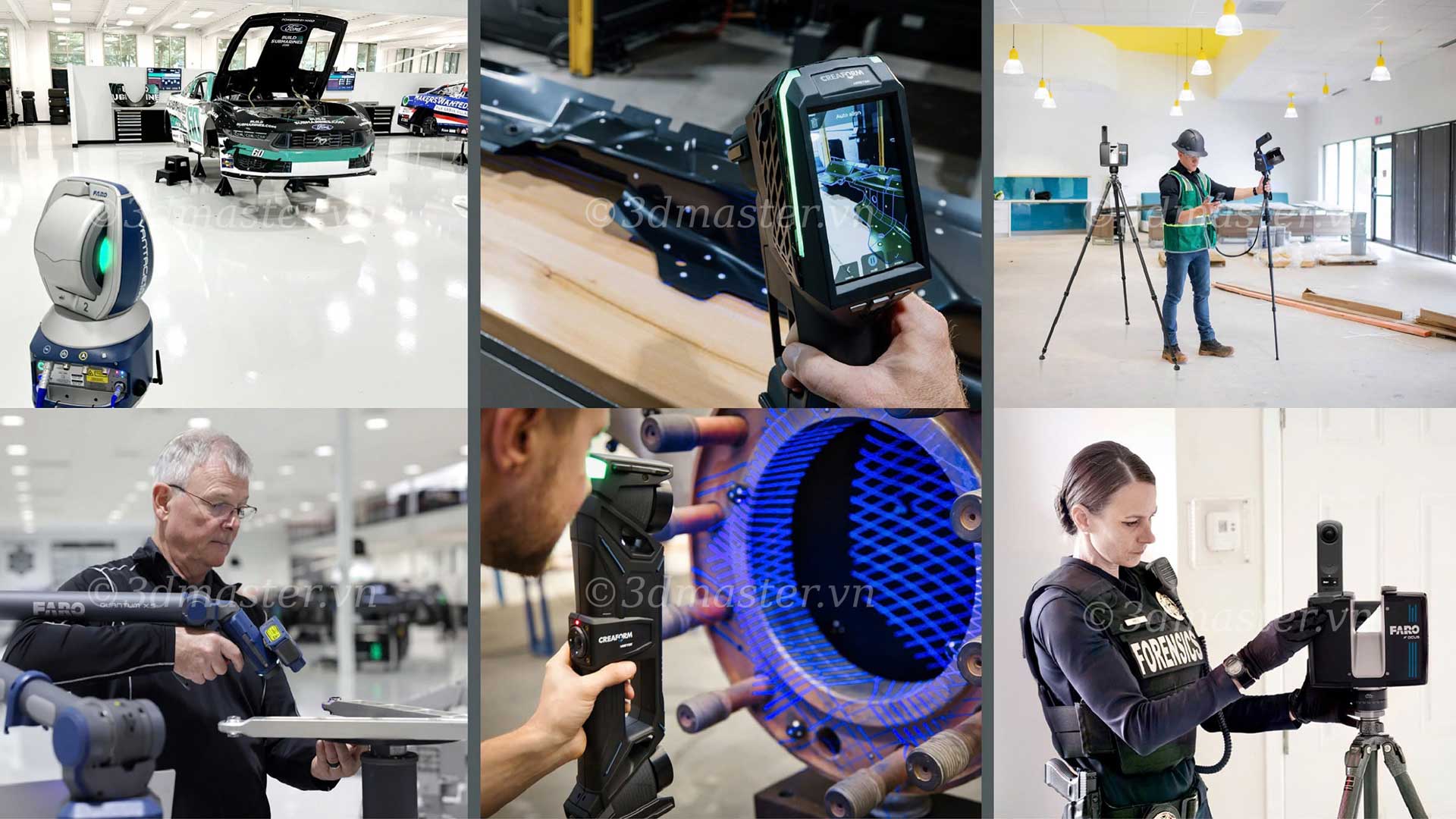
Advanced equipment systems: Equipped with high-performance handheld 3D scanners from FARO Creaform, delivering high measurement accuracy.
Experienced technical specialists: Mechanical engineers provide not only digitized data but also direct support for reverse engineering and manufacturing drawing optimization.
Quality commitment: Fast processing and delivery of accurate files according to technical requirements help businesses shorten product revision lead times.
In summary, when mounting dimensions change, the entire single-stage gearbox drawing does not necessarily need to be recreated. 3D scanning captures the actual geometry, identifies the areas requiring modification, and provides a foundation for CAD model development. Combining scan data with dimensional inspection and engineering evaluation helps minimize machining discrepancies and ensures that the revised design meets the new installation requirements.
Contact 3D Master:
Hotline / Zalo / Telegram / WhatsApp / LINE / Viber / KakaoTalk: +84 982 089 198 | 0986333960
Email: cuong3dmaster@gmail.com | hung3dmaster@gmail.com | tech3dmaster@gmail.com
Website: https://3dmaster.com.vn