In mechanical manufacturing and production line operations, sudden component failures can put entire systems at risk of downtime. For imported, obsolete, or discontinued components, recovering the original technical documentation can be nearly impossible. Today, combining high-precision 3D scanning technology with reverse engineering provides a key solution for recreating accurate CNC drawings, potentially down to the micrometer level under suitable measurement conditions. This approach supports faster component restoration and helps minimize costs.
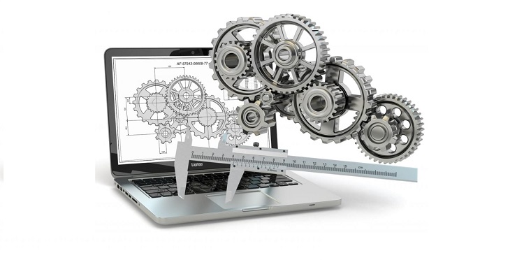
CNC drawings are technical design documents, typically in the form of 2D or 3D CAD models, containing essential information about dimensions, profiles, geometric deviations, surface roughness, and assembly tolerances.
This data is essential for engineers to program toolpaths and motion coordinates for automated machining equipment.
When a mechanical component in a machine fails, reconstructing its technical drawings is critical for several reasons:
Lost original technical drawings: Equipment that has been in operation for many years or purchased from overseas often comes without the original CAD design files, preventing replacement parts from being manufactured.
Discontinued spare parts: The original equipment manufacturer (OEM) may have stopped supplying replacement components, or ordering them may take several months.
Complex component geometry: Freeform surfaces, helical gears, pump impellers, and molds cannot be fully measured manually using calipers and micrometers.
Reduced repair time: Minimizing machine downtime helps businesses restore production lines as quickly as possible.
3D scanning uses optical or laser technology to capture the geometry of physical components. The resulting data can be processed into point clouds or polygon meshes, providing a foundation for reverse engineering.
When combined with CAD software and appropriate measurement procedures, this technology supports the reconstruction of CNC drawings for various mechanical components.
Non-contact 3D scanning technology bridges the gap between a damaged physical object and a high-resolution digital representation.
Accurate, detailed geometric data acquisition: Captures millions of data points across a component's surface in just minutes, including hard-to-reach areas and complex profiles.
3D data generation for analysis: Exports triangular mesh files (STL/OBJ), allowing engineers to assess deformation, wear, or fractures in damaged components against their original geometry.
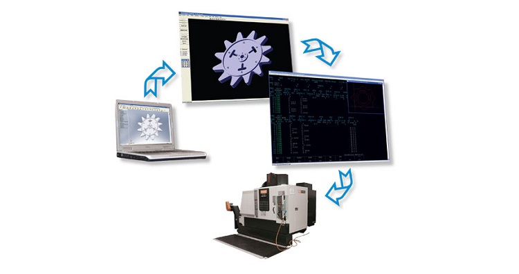
Support for CAD model reconstruction: Provides an accurate geometric reference for reverse engineering, enabling engineers to transform mesh data into parametric CAD surfaces and models (STEP/IGES) for CNC milling drawings or CNC turning drawings.
Improved reconstruction accuracy: Helps reduce cumulative errors associated with traditional manual measurement methods, improving dimensional consistency during assembly.
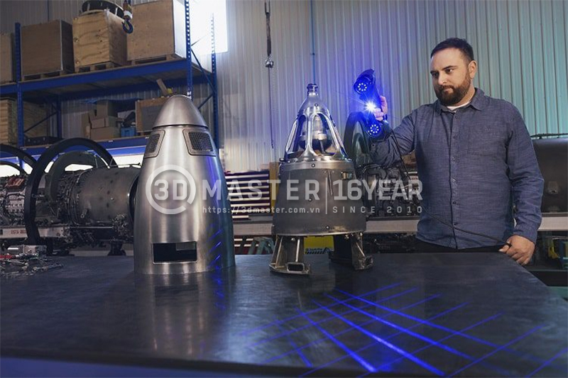
To transform a damaged component into a complete CNC manufacturing file, the process follows six rigorous technical steps:
Step 1: Assess the condition of the component
Clean the surface, identify areas of wear and fracture, and analyze the component's assembly functions and manufacturing material to determine the appropriate restoration strategy.
Step 2: Perform 3D scanning of the component
Use a specialized laser 3D scanner to capture the component's complete three-dimensional geometry with micron-level measurement resolution where supported by the equipment and conditions.
Step 3: Process the scan data
Remove noise, align scans captured from different angles, and optimize the mesh through mesh processing to produce an accurate 3D surface model.
Step 4: Build the CAD model (Reverse Engineering)
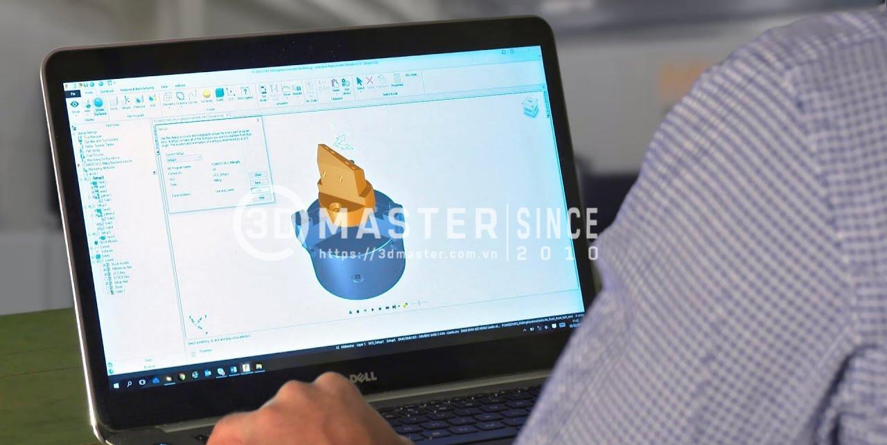
Use specialized software to compensate for missing material, reconstruct worn features, and recreate a complete 3D CAD model.
Step 5: Finalize the CNC drawings
Convert the 3D model into 2D technical drawings, specify geometric dimensioning and tolerancing (GD&T) and surface roughness requirements, and export standardized data for CNC cutting drawings (laser/plasma), CNC turning drawings, or multi-axis CNC milling drawings.
Step 6: Validate the model and perform trial machining
Simulate virtual assembly on a computer, test the CAM program, and manufacture a sample component to verify its actual dimensions.
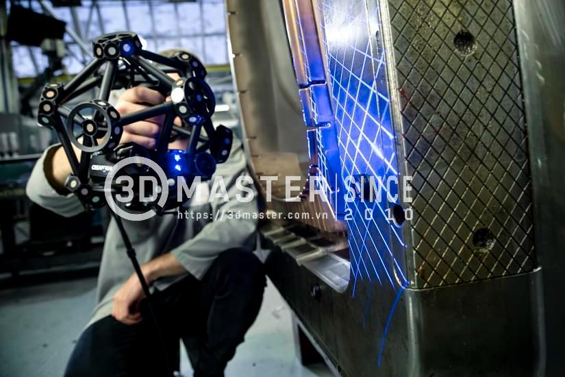
The quality of CNC design documentation for machining depends on the combination of equipment capabilities and the engineering team's expertise:
Equipment accuracy: Industrial 3D scanners with verified performance and accuracy specifications, potentially reaching 0.015 mm under specified conditions, are essential for capturing component dimensions accurately.
Surface condition: Appropriate surface preparation, such as applying a scanning spray to reduce reflections on shiny or transparent surfaces, helps the scanner capture more reliable data.
CAD modeling expertise: Engineers must understand the manufacturer's original design intent to accurately reconstruct hole centers, shoulder diameters, and fillet radii.
Machining and assembly requirements: Properly specifying engineering tolerances on CNC milling or turning drawings helps ensure that machined components function correctly within their assemblies.
Post-machining inspection: Use a CMM or 3D scanner to inspect the finished component and compare the results with the design model.

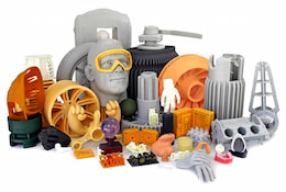

When your production line experiences a sudden spare-part failure, 3D Master offers comprehensive digitization and mechanical reconstruction solutions designed to help businesses restore operations quickly and accurately in Vietnam.
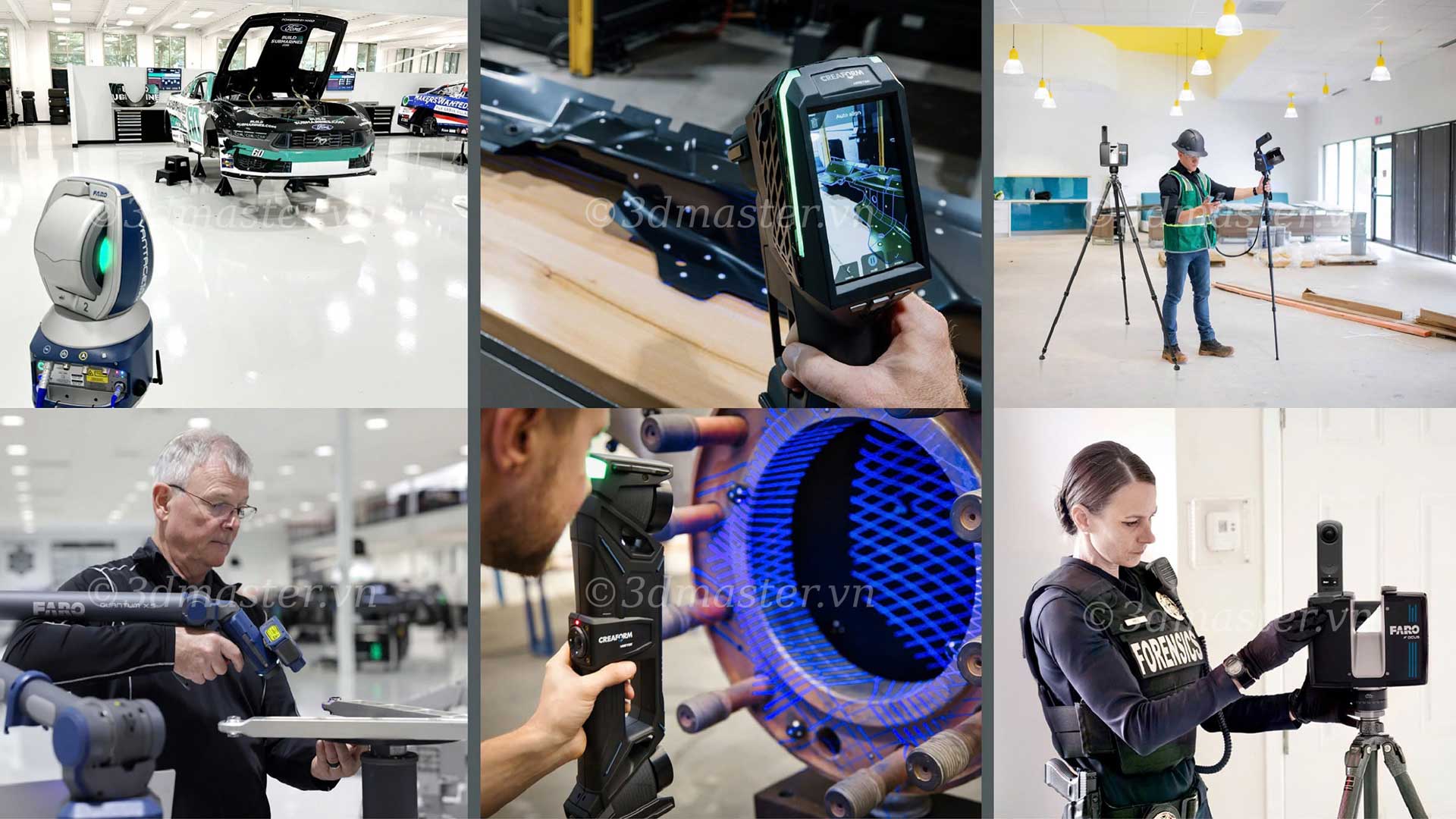
Advanced equipment: 3D Master provides access to modern industrial laser 3D scanning systems from FARO and Creaform, with accuracy specifications reaching 0.015 mm for suitable equipment and measurement conditions, supporting demanding precision engineering applications.
Experienced engineering team: Reverse engineering specialists with more than 10 years of experience in metrology understand manufacturing principles and can reconstruct CNC drawings suitable for machining requirements.
Comprehensive solutions: Reconstructs everything from CNC cutting drawings for thin sheet metal and CNC turning drawings for rotational components to complex 3D, 4D, and 5D CNC milling models and toolpaths, depending on project requirements.
Cost and time optimization: On-site services and efficient data processing help businesses reduce costs and lead times compared with sourcing new imported components. Actual savings depend on the component and project scope.
Reconstructing CNC drawings using 3D scanning enables businesses to recover technical data, manufacture replacement parts, and reduce production downtime when original drawings are missing. By combining suitable scanning equipment with professional reverse engineering and inspection procedures, businesses can improve CAD model accuracy and machining quality. Contact 3D Master for advice on 3D scanning, technical drawing reconstruction, and practical applications in mechanical manufacturing.
3D Master Contact Information:
Hotline / Zalo / Telegram / WhatsApp / LINE / Viber / KakaoTalk: +84 982 089 198 | 0986333960
Email: cuong3dmaster@gmail.com | hung3dmaster@gmail.com | tech3dmaster@gmail.com
Website: https://3dmaster.com.vn