Bridge and road inspection is essential for assessing existing conditions, monitoring changes, and supporting the transportation infrastructure maintenance process. However, bridge surveys often face challenges due to complex structures, inaccessible locations, and the need to minimize disruption to traffic. 3D scanning technology offers a method for rapidly collecting as-built data, providing a basis for measurement, analysis, and infrastructure modeling. By combining stationary and mobile 3D scanning, surveying teams can work more flexibly when capturing data across the entire bridge.
Bridge and road inspection is the process of surveying, measuring, assessing, and recording the condition of bridges and their associated components.
The objective is to determine the current condition of the infrastructure, identify signs of damage, monitor changes, and provide data for maintenance and repair.
The inspection items should be selected based on the structural characteristics, current condition, and survey objectives.
Structural inspection: Assess components such as the bridge deck, girders, piers, abutments, and bearing systems. Record signs of cracking, deformation, spalling, or other damage for further evaluation.
Topographic survey: Collect terrain data, elevations, and information about the surrounding areas to assess ground conditions, adjacent areas, and the overall project boundaries.
Geometric inspection: Measure length, width, height, span, and the relative positions of structural components to compare actual dimensions with the design documentation.
As-built modeling: Reconstruct the structure's geometry in drawings or a 3D model, providing a reference for renovation, repair planning, and infrastructure management.
Monitoring and maintenance: Store data from successive surveys for comparison, identify geometric changes, and help determine the need for more detailed inspections.
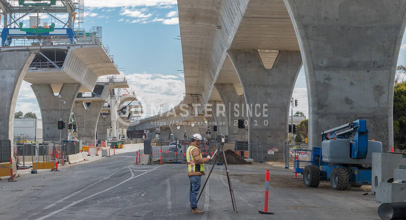
Bridges and roads often involve large-scale structures, complex geometries, and many inaccessible locations. When using manual measurements or conventional surveying equipment, technicians may need to establish numerous measurement points, move equipment repeatedly, and combine multiple methods to collect sufficient data.
Common challenges encountered during bridge and road surveys include:
Difficult access to inspection locations: Areas beneath bridges, the sides of girders, bridge piers, or locations above rivers may require specialized equipment and dedicated access solutions.
Environmental impacts: Strong winds, water levels, currents, vegetation, and traffic volumes can interfere with surveying activities.
Time-consuming measurements: Measuring individual points across large structures requires numerous operations. Relocating equipment and verifying measurements can extend survey time.
Difficulty capturing comprehensive site conditions: Discrete measurements may not fully represent surface geometry or the spatial relationships between structural components.
These challenges highlight the need for a fast, systematic data collection method that also allows survey data to be reused after fieldwork. 3D scanning technology is a practical solution worth considering to meet these requirements.

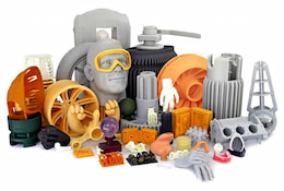
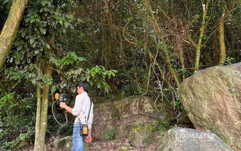
3D scanning technology uses optical or laser sensors to collect the coordinates of numerous points on a structure's surface.
These data points are compiled into a 3D point cloud representing the geometry and relative positions of the scanned areas. Based on this data, technicians can perform measurements, build models, and compare existing conditions according to project objectives.
In bridge and road inspection, 3D scanning technology offers several key benefits:
Spatial data collection: Capture three-dimensional coordinates to reconstruct the geometry and relative positions of bridge components.
Detailed condition documentation: Collect structural surface data to support the examination of geometry and features within the scanned area.
Reduced survey time: Capture numerous data points simultaneously, reducing manual measurement tasks and the need to repeatedly reposition equipment.
Support for change detection: Compare data from different scanning sessions to identify geometric or positional changes in structural components.
Data for analysis: Convert point clouds into drawings and 3D models to support measurement, repair, and infrastructure management.
It is important to note that 3D scanning primarily captures surface geometry and cannot independently determine the full causes or severity of internal structural damage.
To assess bridge safety, engineers must combine scanning data with visual inspections, non-destructive testing, load testing, or other specialized inspection methods when necessary.
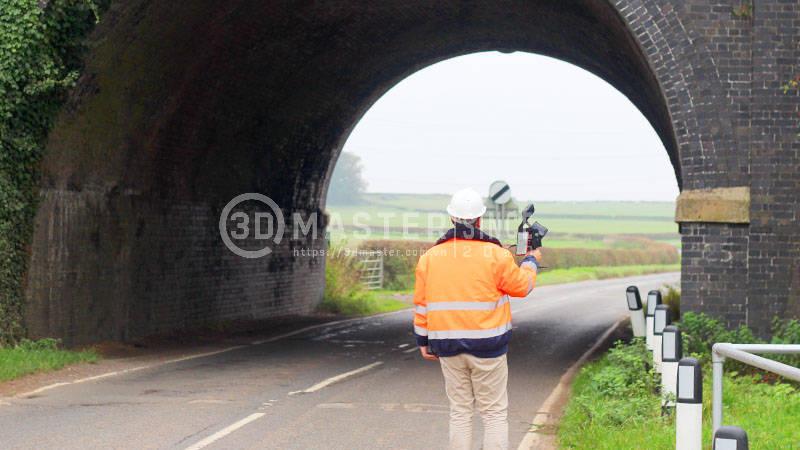
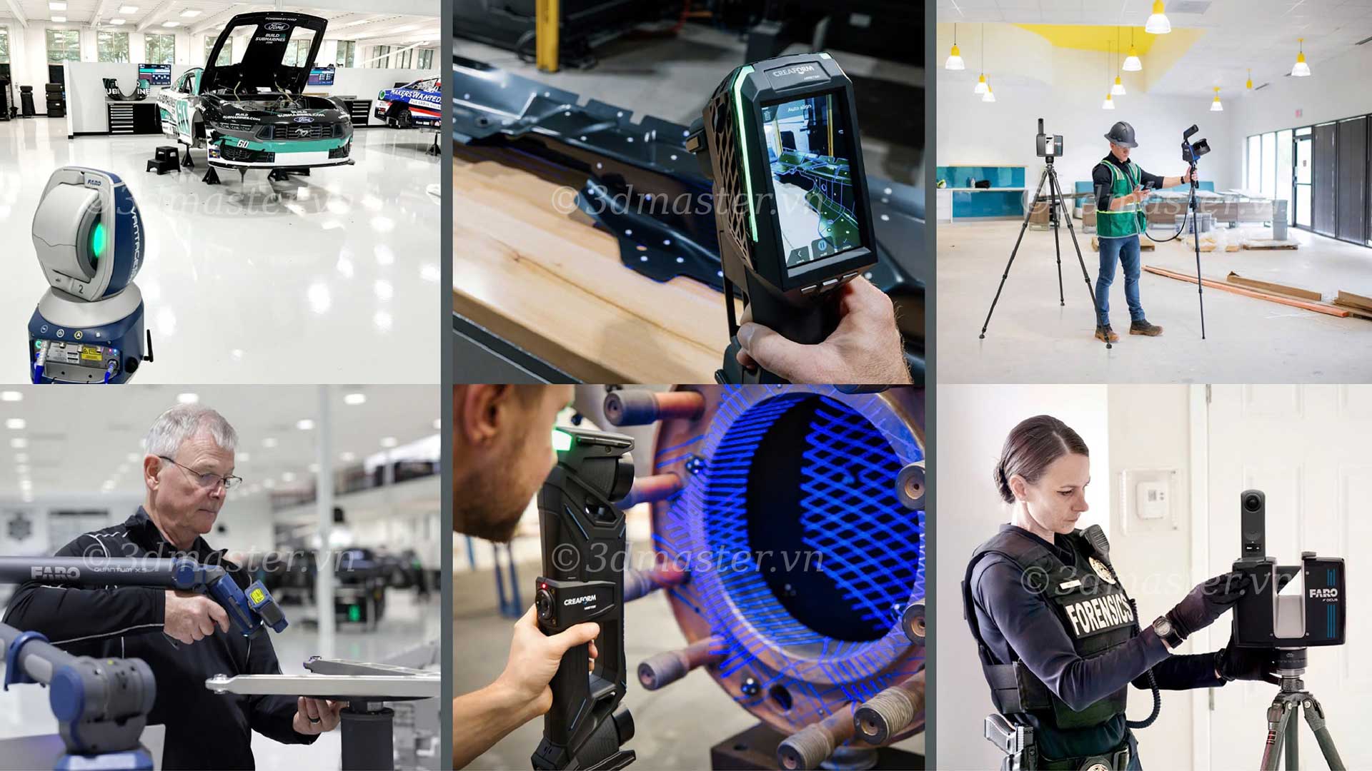
Stationary 3D scanning involves positioning a scanner at a fixed location to collect spatial data from the surrounding area. Technicians can establish multiple scanning positions to capture different areas and register the datasets into a unified system.
This method is suitable when detailed geometric information about bridge structures is required or when developing as-built documentation for measurement and analysis.
Capturing areas requiring high detail: Select appropriate scanning positions to collect data from girders, piers, abutments, and other components that require specific inspection.
Supporting geometric measurements: Use point clouds to measure dimensions, examine geometry, and determine the relationships between components within the captured dataset.
Combining data from multiple positions: Perform multiple scans, then align and merge the datasets to create an overall model. The quality of the results depends on the data registration method and error control.
One limitation of this method is the need to select and arrange suitable scanning positions. For long bridges or structures with many areas requiring inspection, the number of equipment relocations and setup operations may increase.
Mobile 3D laser scanning collects data while the scanning device moves along the survey area.
Some systems use simultaneous localization and mapping (SLAM) technology to determine the movement trajectory and build spatial data without stopping at every point, as is typically required with stationary scanning.
This method is suitable for long structures, large survey areas, or locations where multiple positions need to be documented during a single pass.
Surveying along the structure: Collect data from bridge decks, approach roads, and accessible areas while moving through the site.
Expanding data coverage: Support surveys of long or continuous areas, helping create an overview of the structure and its surrounding environment.
Reducing equipment setup operations: Minimize the need to stop and set up equipment at individual positions, potentially shortening data collection time.
Flexibility in field conditions: Depending on the system and deployment method, the equipment can be carried by an operator or mounted on a vehicle to access suitable areas.
The accuracy of mobile scanning data depends on the equipment, movement trajectory, environmental conditions, localization capabilities, and data control methods. Therefore, technical requirements should be evaluated before selecting a scanning approach.
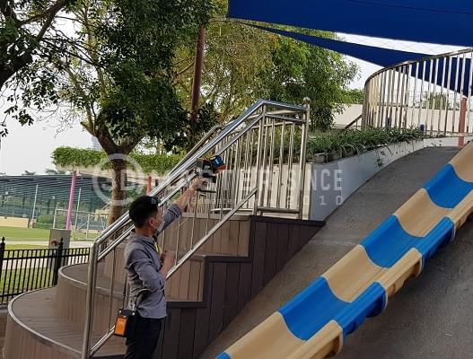
Combining stationary and mobile 3D laser scanning takes advantage of the wide-area coverage of mobile systems and the detailed data capture provided by stationary systems at selected locations.
The combined workflow can be implemented as follows:
Mobile scanning for overall data capture: Collect data along the bridge and across accessible areas to establish a baseline dataset for the entire survey area.
Stationary scanning at critical locations: Supplement the dataset at components requiring greater detail or in areas where mobile scanning data do not meet the required specifications.
Data alignment and integration: Transform the datasets into a unified coordinate system, check deviations, and generate an overall point cloud.
Analysis based on project objectives: Use the processed data to perform measurements, develop as-built models, and support change monitoring across successive surveys.
The combined approach should be designed according to bridge length, structural characteristics, site accessibility, and required accuracy. Not every project requires both scanning methods.
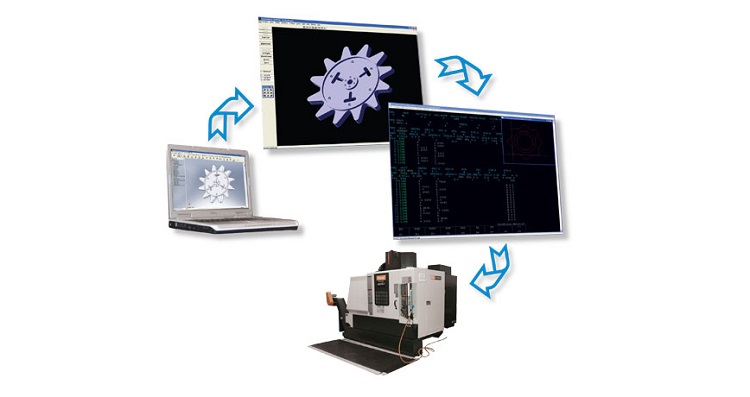
Specialized software helps align multiple scans, verify data quality, and convert point clouds into drawings or models that meet survey objectives.
Key tasks include:
Point cloud processing: Align and merge data from multiple scanning positions. Remove noise points, check for missing data, and assess the quality of the results.
Measurement and analysis: Determine dimensions, elevations, geometry, and distances between components within the captured dataset.
Creating drawings and 3D models: Convert scanning data into as-built drawings or three-dimensional models for infrastructure management, design, repair, and renovation.
Data integration: Export data to compatible design, modeling, or infrastructure management software. The output format should be selected according to the end user's requirements and the project's technical workflow.
To ensure that the results are suitable for practical use, errors must be controlled during scanning, data registration, and processing.
A 3D model only reflects the information captured and processed from the input data. Therefore, it should not be considered a structural inspection conclusion unless it has been evaluated by qualified specialists.
3D scanning can improve the collection and management of as-built data, but its effectiveness depends on equipment selection, survey planning, and quality control.
Before implementation, the intended use of the data should be clearly defined to ensure that the appropriate technology and processing workflow are selected.
Define the survey scope: Identify the areas to be scanned, components requiring measurement, required level of detail, and data deliverables.
Select the appropriate technology: Consider stationary scanning, mobile scanning, or a combination of both based on bridge size, accessibility, and technical requirements.
Control measurement accuracy: Establish suitable control points, minimize occluded areas, and check errors during data registration.
Ensure on-site safety: Develop an access plan, arrange equipment, and coordinate traffic management when necessary.
Combine with specialized inspections: When internal damage or load-bearing capacity needs to be assessed, appropriate structural inspection methods must also be applied.
Choose a technically qualified service provider: Prioritize providers with suitable equipment, clearly defined survey procedures, and the ability to process data according to project requirements.
3D Master provides 3D scanning, 3D measurement, and data processing services tailored to customers' actual requirements. The company has experience implementing 3D scanning applications in industrial, construction, topographic surveying, and spatial digitization projects.
In conclusion, 3D scanning technology offers a more efficient approach to bridge and road inspection by reducing data collection time, capturing detailed existing conditions, and supporting structural change monitoring. To maximize its benefits, the appropriate scanning method must be selected, and data quality must be controlled throughout each project. Contact 3D Master for consultation on 3D scanning, as-built digitization, and data processing solutions tailored to your infrastructure requirements.
3D Master Contact Information:
Hotline / Zalo / Telegram / WhatsApp / LINE / Viber / KakaoTalk: +84 982 089 198 | 0986333960
Email: cuong3dmaster@gmail.com | hung3dmaster@gmail.com | tech3dmaster@gmail.com
Website: https://3dmaster.com.vn