In industrial manufacturing, CNC machining plays a central role in producing and restoring high-precision machine components. However, when long-serving machine shafts become damaged or worn, custom CNC machining for replacement parts can be challenging due to the lack of original design drawings. A promising solution is to apply 3D scanning technology to reconstruct drawings of worn machine shafts before CNC machining. By combining reverse engineering with CNC milling or CNC turning, even complex one-off CNC machining orders for restoring machine components can be handled effectively, ensuring compliance with engineering tolerances and optimizing operating costs.
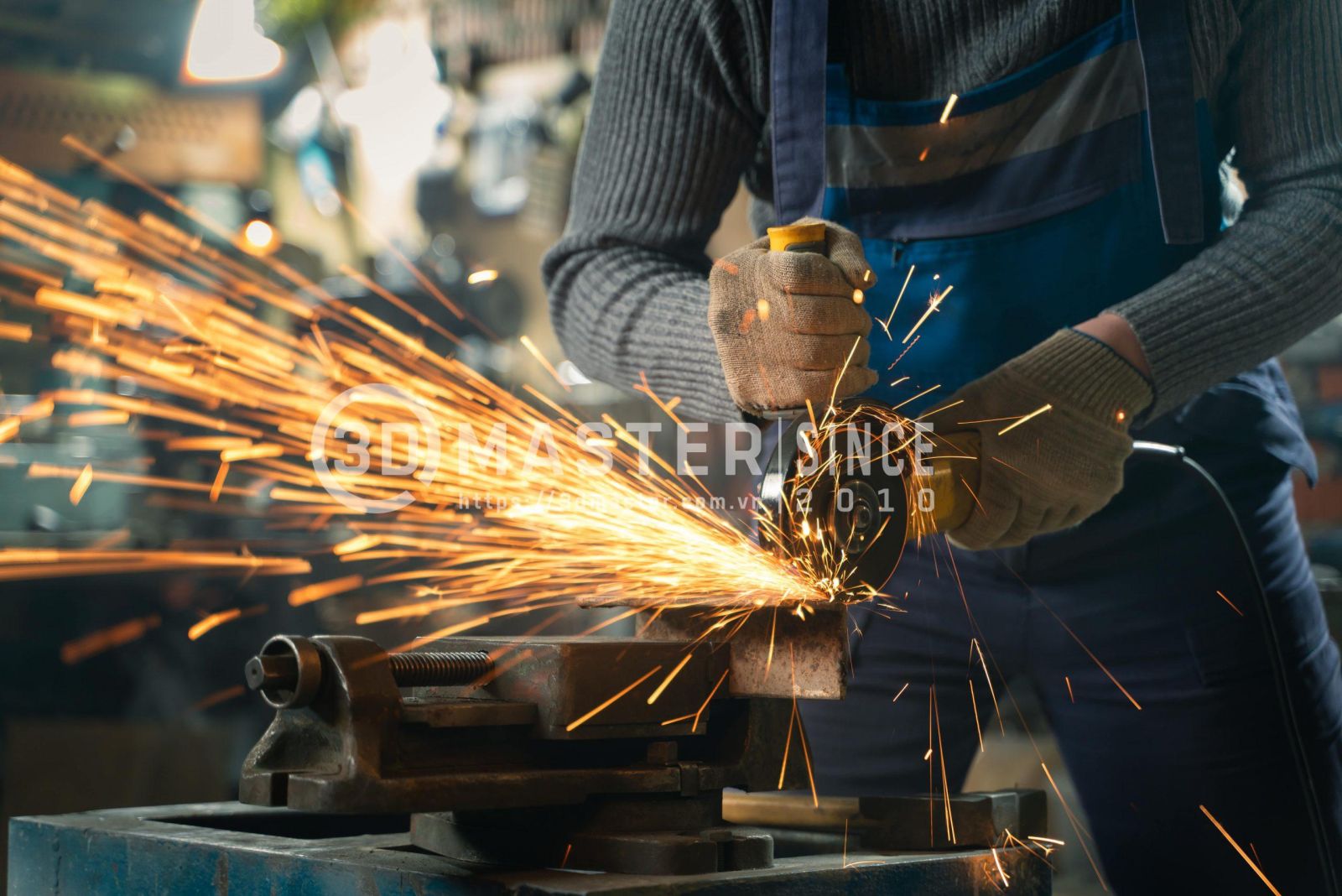
Machine shaft wear refers to the reduction in dimensions and deformation of shaft journals and shoulders caused by friction, loads, and heat during operation.
Common types of damage include journal wear caused by friction against bearings, bushings, or seals; uneven wear resulting from loading conditions and lubrication; and shaft bending caused by overloading, impact, or thermal effects.
Shaft wear reduces concentricity, causes severe vibration, damages bearings, and can bring the entire production line to a halt.
Without the original drawings, restoring worn machine shafts presents several engineering challenges:
- Challenges in material selection and thermal deformation: Selecting compatible materials can be difficult, while weld buildup may introduce residual stress and thermal distortion.
- Challenges in establishing reference centers and concentricity: Unevenly worn shaft journals make it extremely difficult to fixture the part on a CNC machine and re-establish its original reference axis.
- Challenges involving fit tolerances and surface finish: It is difficult to accurately determine the original fit tolerances, such as k6 and h6, on surfaces that have already been deformed.
- Challenges involving complex geometries and intricate features: Features such as keyways, special threads, and cam lobes may have lost their original profiles, complicating machining programming.
- Time and cost pressures for one-off repairs: Manual alignment and setup are time-consuming, while the risk of damaging the workpiece increases costs associated with machine downtime.
Traditional methods rely on manual measurements, which can easily miss deviations on worn shafts. In contrast, 3D scanning captures more comprehensive surface data, supporting damage analysis and CAD model reconstruction before CNC machining.
- Comprehensive geometric data capture with high accuracy: Captures detailed 3D surface data with micrometer-level precision (µm).
- Clear and accurate wear analysis: Generates a color map that clearly identifies the locations and extent of actual wear.
- Accurate resolution of reference-axis and runout issues: Automatically calculates and reconstructs the original theoretical axis with greater accuracy.
- Time savings and reduced subjective measurement errors: Captures data within minutes, minimizing errors associated with manual measurements.
- Creation of a digital archive: Converts scanned data into 3D CAD files for easy storage and future reproduction.
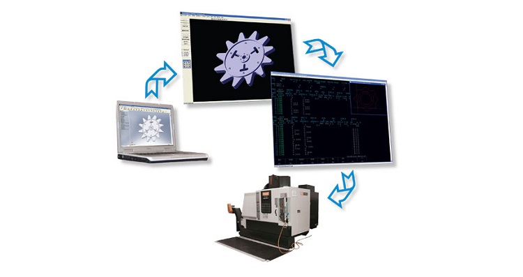
- Seamless integration with CAM/CNC programming: Transfers CAD models directly into CAM software for faster CNC milling and turning programming.
To reconstruct machine shafts for manufacturing, scan data must be combined with mechanical design expertise and an understanding of the component's actual operating requirements.
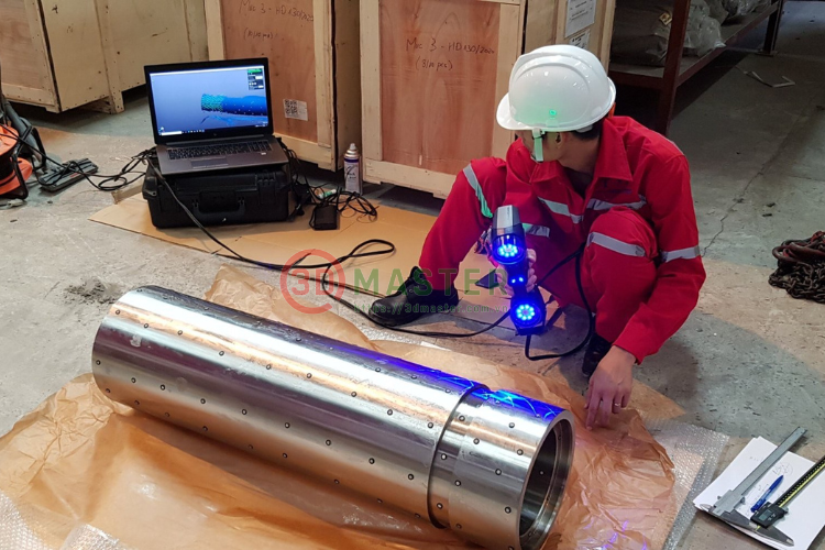
Thoroughly clean oil, grease, and rust from the shaft surface. Attach reference targets to the shaft or fixture to help the 3D scanner determine its spatial position. Apply a thin layer of scanning spray if the shaft surface is excessively shiny or highly reflective.
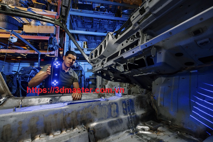
Use a specialized 3D scanner to project laser beams or structured light onto the machine shaft. The device captures millions of 3D spatial data points to reconstruct the surface as a triangular mesh (STL/OBJ).
Import the mesh data into 3D processing software to remove noise, fill holes, and align the coordinate system. Engineers then analyze wear by comparing geometric cross-sections to determine the original nominal dimensions.
Based on the processed mesh data, engineers reconstruct a 3D CAD model (parametric solid model). Worn surfaces are recreated according to their intended geometric forms, including cylinders, planes, threads, and grooves. Dimensions are then standardized according to mechanical industry fit requirements.
Generate a 2D engineering drawing from the completed 3D CAD model. Specify all dimensions, fit tolerances, geometric tolerances such as runout, concentricity, and roundness, as well as surface roughness (Ra).
Transfer the CAD/CAM files to the machining workshop. Program toolpaths for CNC turning or milling machines, then manufacture the actual component through CNC machining. Finally, use 3D scanning again for inspection, comparing the finished part against the design drawing.


When reconstructing drawings of worn machine shafts, engineers must strictly control the following technical parameters:
- Shaft journal diameter and fit tolerances: Determine the appropriate fit type to specify journal diameter tolerances compatible with rolling bearings or bushings.
- Concentricity and runout: Strictly control concentricity between bearing journals, as well as axial-face and radial runout, to reduce the risk of fatigue failure during high-speed rotation.
- Roundness and cylindricity: Ensure that geometric deviations of cylindrical surfaces do not exceed half the corresponding diameter tolerance range.
- Fillet radii and shaft shoulders: Reconstruct the correct fillet radius at diameter transitions to minimize stress concentration and prevent shaft cracking or fracture.
- Keyways, splines, and threads: Accurately verify thread pitch, keyway angles, and keyway symmetry relative to the shaft axis.
- Material and heat treatment: Analyze the original material, such as C45, 40Cr, or SCM440 steel, to determine the appropriate heat treatment method, including induction hardening, carburizing, or quench-and-temper treatment, to achieve the required HRC hardness.
- Model verification and adaptability: Ensure that the reconstructed CAD model is parametric so that it can be adjusted easily if the machining workshop needs to modify the stock allowance.
As a leading provider of 3D metrology and industrial digitization solutions in Vietnam, 3D Master offers comprehensive solutions for restoring damaged and worn machine components:
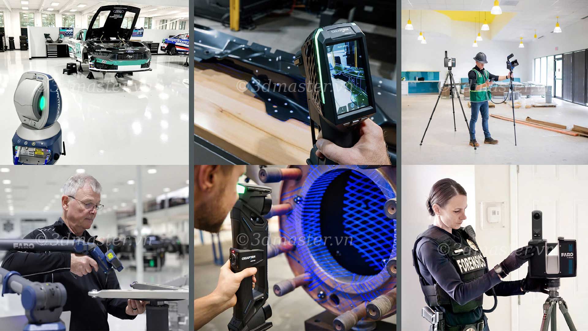
- Modern equipment: Equipped with advanced laser 3D scanners from FARO and Creaform, as well as portable coordinate measuring machines (CMMs), with accuracy down to 0.015 mm.
- Specialized engineering team: Engineers with over 10 years of experience and in-depth knowledge of tolerances, materials, and CNC machining technology.
- Flexible machining services: Promptly handles one-off CNC machining orders, urgent repairs, and large-volume custom CNC machining requirements.
- Integrated and optimized workflow: Provides comprehensive support from 3D scanning and CAD/CAM to CNC milling/turning consultation and quality control (QC).
3D Master can recommend an appropriate scanning method based on the component's characteristics and the intended use of the data. Businesses should provide photographs, key dimensions, the current condition of the damaged part, and fit requirements so that the technical approach can be evaluated before implementation.
In conclusion, combining 3D scanning with reverse engineering enables more accurate reconstruction of drawings for worn machine shafts, reduces measurement time, and provides reliable input data for CNC machining. For components that are difficult to measure or lack original drawings, 3D Master provides 3D scanning and custom CAD modeling solutions to help businesses restore parts and optimize machining processes.
Contact Information – 3D Master:
Hotline / Zalo / Telegram / WhatsApp / LINE / Viber / KakaoTalk: +84 982 089 198 | 0986333960
Email: cuong3dmaster@gmail.com | hung3dmaster@gmail.com | tech3dmaster@gmail.com
Website: https://3dmaster.com.vn