3D scanning technology for casting inspection helps detect dimensional deviations, evaluate machining allowances, and control quality before parts proceed to the next manufacturing stage. By combining a 3D scanner with CAM2 software, businesses can compare actual measurement data with CAD models, analyze defects, and optimize production processes. This solution helps reduce scrap, minimize rework costs, and improve foundry productivity.
A casting is a product created by pouring molten metal into a mold and allowing it to cool and solidify into the shape of the mold cavity. After removal from the mold, the casting may undergo additional machining to achieve the dimensions and accuracy required by technical specifications.
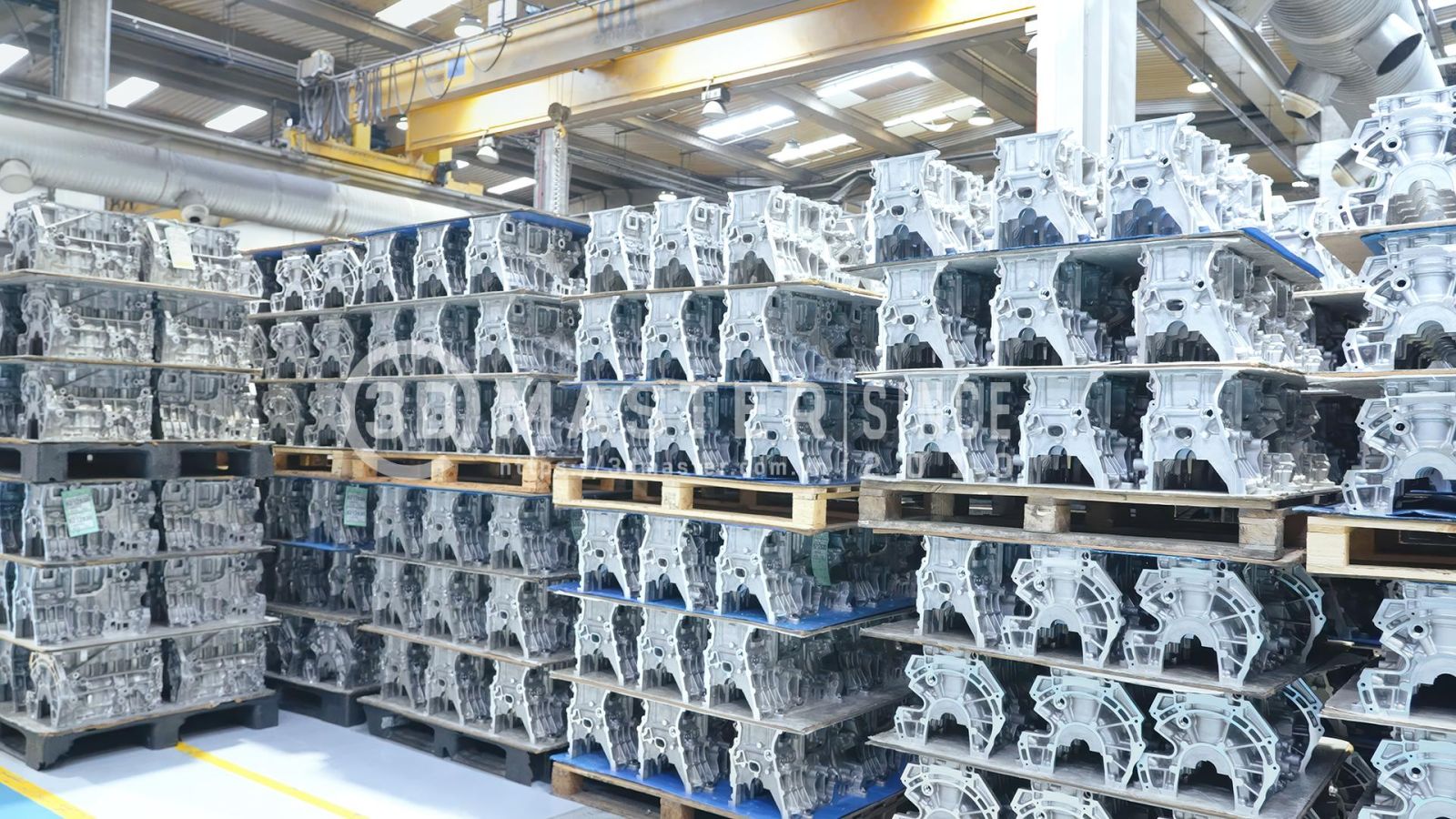
In the metal casting industry, visual inspection alone is insufficient to accurately determine the quality of a component. A product may pass visual inspection but still exhibit dimensional deviations during machining.
This can occur in various components, ranging from engine blocks, valve bodies, and railway couplings to wind turbine impeller shafts, pipe fittings, marine propellers, and aircraft structures.
According to some estimates, the global metal casting market could reach USD 300 billion by 2026. Amid intensifying competition, issues such as insufficient machining allowance, deformation, and dimensional deviations can increase costs and affect production schedules.
If not detected early, these deviations can lead to wasted materials, machine operating time, and production capacity. Therefore, the goal is not simply to measure cast components but also to accurately identify the locations of deviations from the outset. This enables businesses to make timely adjustments and minimize defects in subsequent production stages.
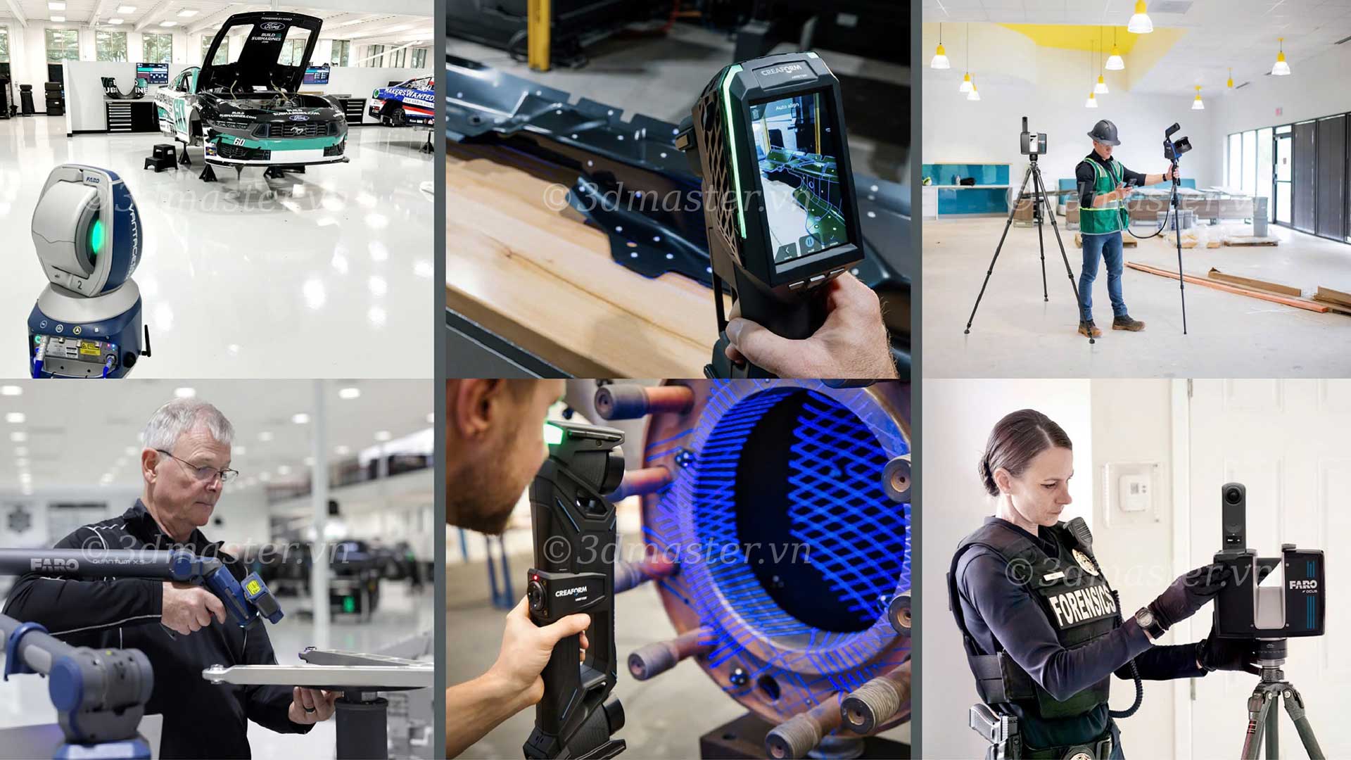
Advanced metrology software, such as FARO CREAFORM's CAM2, can process, visualize, and analyze data collected using portable coordinate measuring arms and handheld 3D laser scanners. This enables businesses to assess component quality and detect deviations more efficiently.
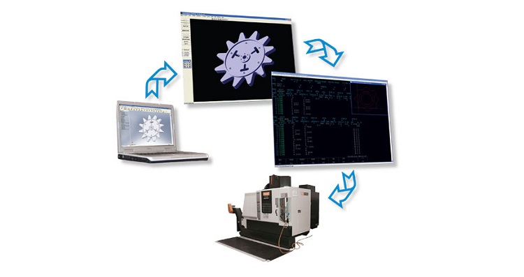
3D scanning metrology equipment is only one part of the process. When combined with specialized software, measurement data is transformed into visual information, helping technicians reduce inspection time, assess quality more accurately, and retrieve results easily. This also provides a basis for making appropriate decisions at each stage of production.
In other words, software helps businesses maximize the value of their metrology equipment. Rather than simply collecting data, businesses can use it to control quality, improve processes, and minimize errors.
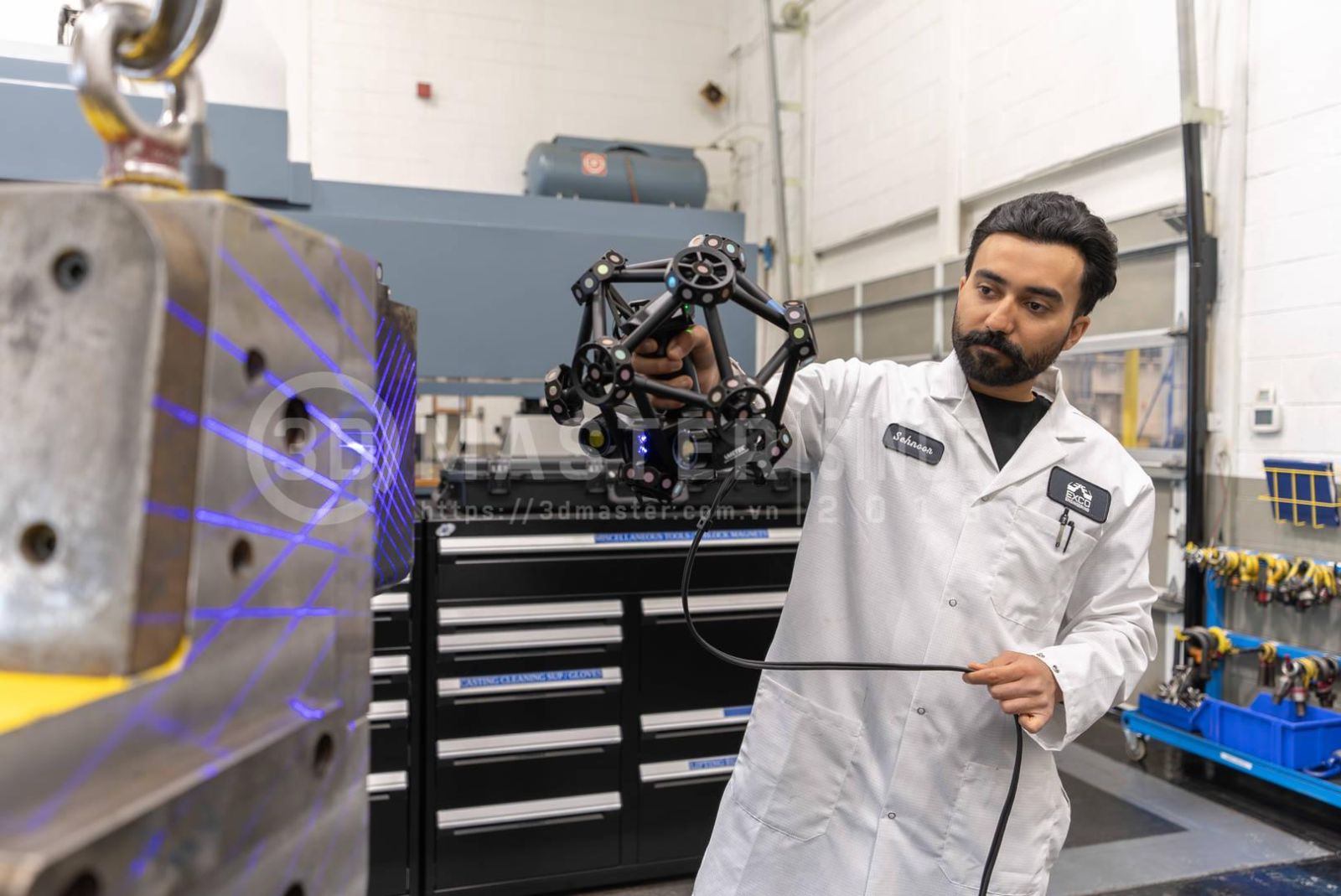
CAM2 is a metrology software solution compatible with FARO CREAFORM handheld 3D scanners and portable measurement equipment. Compatible equipment includes FARO measuring arms, laser tracker systems, HandySCAN 3D handheld laser scanners, and other coordinate measurement systems.
The software helps manufacturers, quality management teams, and metrology professionals inspect components, verify dimensions, compare physical objects with CAD models, and generate detailed inspection reports.
With its modular design, CAM2 allows users to select functions suited to their metrology and quality control requirements rather than investing in a fixed solution for every situation.
Instead of requiring operators to analyze millions of data points manually, CAM2 organizes measurement information into intuitive visual comparisons, deviation color maps, statistical analyses, and automated reports. This makes it easier to identify deviations and problems arising during production.
By collecting comprehensive and accurate 3D scan data from casting surfaces at different production stages, 3D scanners combined with software such as CAM2 help foundries optimize tooling and mold verification, quality control, defect analysis, and reverse engineering of existing components.
Whether used for prototyping, casting inspection, or wear monitoring, 3D metrology solutions and specialized software are increasingly becoming essential tools in manufacturing metrology equipment portfolios.
One of the biggest challenges manufacturers face when working with cast or forged components is ensuring that sufficient material remains in the required areas for machining before cutting begins.
The latest improvements to CAM2's inspection capabilities help users confidently position, analyze, and digitally verify cast components before any cutting operation takes place.
The benefits are clear: reduced scrap, fewer machining errors, faster data-driven decision-making, and fully traceable inspection reports.
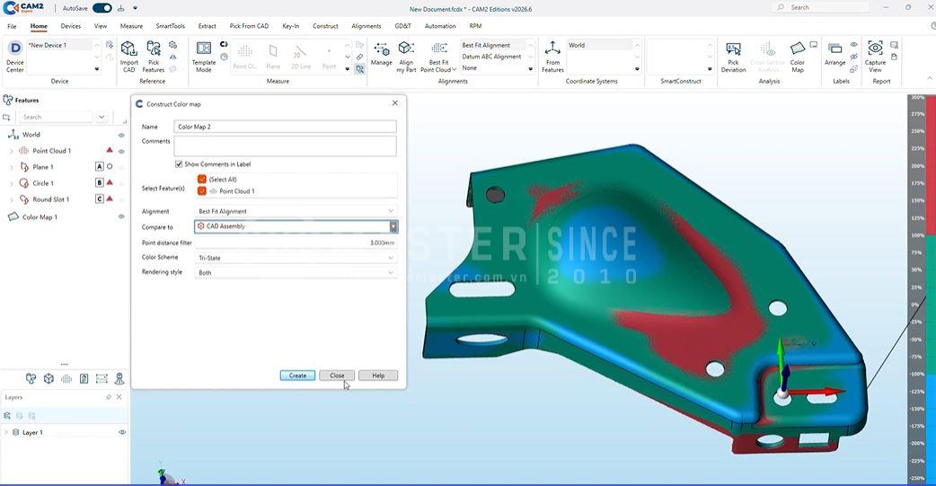
The Advanced Color Map feature helps users visually identify deviations between 3D scan data and CAD models. Deviations are represented by different colors, allowing technicians to quickly locate areas requiring inspection.
Users can generate multiple color maps with different alignment methods and compare scan data against the entire CAD model or specific surfaces. The software also allows users to set individual tolerances for each surface and customize colors according to whether measurements fall within or outside acceptable limits.
Combined with reporting tools, this feature enables technicians to quickly identify problem areas, compare results across different alignment methods, and clearly document deviations.
As a result, production teams can assess casting quality more easily, communicate findings more accurately, and make timely decisions before components proceed to machining.
Cross-section analysis is a method of evaluating casting geometry through a section or slice passing through a component. This method helps reveal internal geometry, wall thickness, transition areas, reinforcing ribs, cavities, and other features that cannot be observed from the outside.
The latest feature updates introduce improved tools for creating and analyzing cross-sections without physically cutting the component. Users can extract actual geometry from scan data while calculating theoretical geometric characteristics directly within the software.
With information that can be applied directly to practical manufacturing tasks, foundry personnel can verify critical dimensions against design requirements, conduct more detailed inspections, and generate accurate measurement data ready for reporting.
Smart Alignment enhances the alignment of point clouds with CAD models. This feature helps align difficult-to-process components and distribute excess material around the nominal CAD model.
The enhanced optimal alignment function is designed to deliver more stable and reliable alignment results for complex or symmetrical components.
Users can perform multiple alignments simultaneously with different algorithms and parameter sets, then automatically select the optimal result based on empirical rules and statistical evaluations. The feature can also detect and compensate for symmetry-related factors to reduce the risk of incorrect alignment.

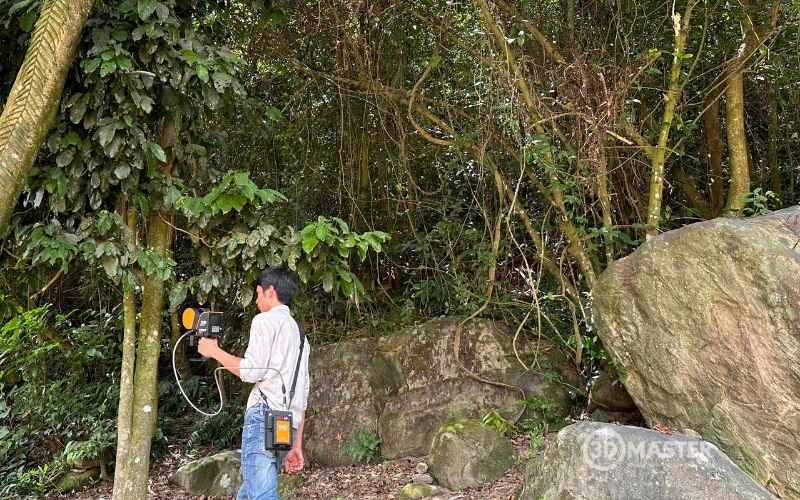
As professionals in the foundry industry know, metal casting involves multiple stages, each requiring precision. The process begins with the production of patterns, tooling, and casting molds.
Other stages include:
Prototype verification, first article inspection, and quality control
Casting performance evaluation and process optimization
Failure analysis and wear monitoring
Reverse engineering
As mentioned earlier, CAM2 is more than just an inspection software solution. By combining scan data, CAD models, dimensional inspection results, and reporting tools within a single environment, the software helps foundries make faster, more accurate decisions while improving coordination among engineering, mold manufacturing, quality management, and production teams.
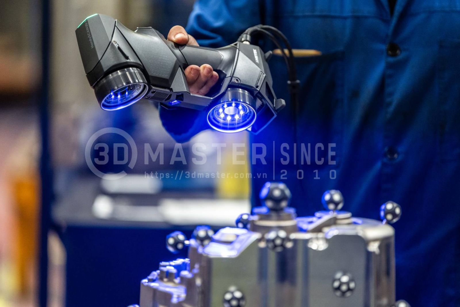
As with other manufacturing processes, integrating 3D inspection at critical stages offers numerous benefits for subsequent production operations.
For foundries, this increases confidence that castings meet specifications, contain sufficient material for subsequent operations, including machining, and are ready to proceed to the next manufacturing stage with minimal risk of costly quality defects.
- Pattern, tooling, and mold inspection: Compare scan data with CAD models to detect geometric deviations, identify areas with excess or insufficient material, and locate areas requiring adjustment.
- Prototype verification and quality control: Inspect trial castings and first articles against design requirements; store data and reports for traceability and comparison.
- Casting process optimization: Analyze measurement data across multiple inspections to detect deviations, signs of shrinkage, or mold shifts and identify processes requiring improvement.
- Defect analysis: Compare scan data with CAD models and previous inspection results to identify deviations, support root cause analysis, and select corrective measures. 3D scanning primarily evaluates surface geometry and does not replace methods for detecting internal defects.
- Reverse engineering: Digitize existing components or tooling to reconstruct CAD models, restore geometry, and update drawings for machining and design improvements.
From accelerating first article inspections to ensuring tighter tolerances when verifying finished castings, 3D measurement analysis and visualization software, together with data acquisition equipment, have become essential enabling technologies. By shortening inspection time and improving casting quality, foundries can streamline workflows, detect defects earlier, and minimize repair and rework costs.
Beyond casting inspection, 3D metrology software can be applied throughout the manufacturing process, making it a valuable investment with significant potential returns. With such a broad range of applications, CAM2 is increasingly becoming an important tool in helping the foundry industry achieve higher productivity, greater accuracy, and greater flexibility in an increasingly competitive market.
3D Master Contact Information:
Hotline / Zalo / Telegram / WhatsApp / LINE / Viber / KakaoTalk: +84 982 089 198 | 0986333960
Email: cuong3dmaster@gmail.com | hung3dmaster@gmail.com | tech3dmaster@gmail.com
Website: https://3dmaster.com.vn