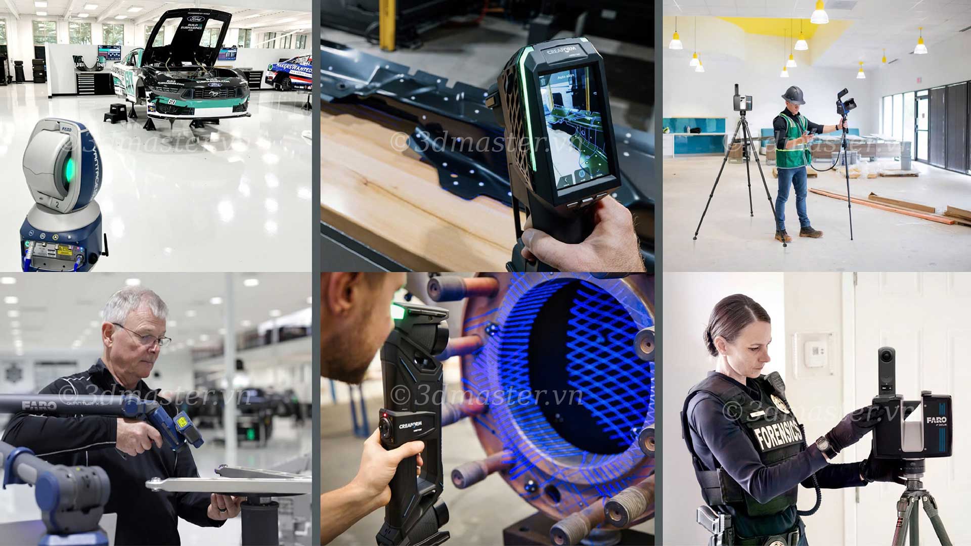
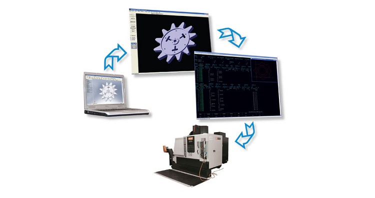
The marine propeller shaft system transmits torque from the engine to the propeller to generate thrust for the vessel. After prolonged operation, components may experience wear, corrosion, deformation, or geometric deviations that affect operating performance. Inspection using 3D scanning and a 3D CMM machine helps assess surface conditions efficiently and accurately evaluate dimensional and geometric deviations. This supports the identification of areas requiring repair, quality control after machining, and improved reliability of the propulsion system.
3D inspection is the process of collecting and analyzing geometric data of a component in three-dimensional space. This method uses equipment such as 3D scanners or 3D CMM machines to inspect dimensions, shapes, and deviations from reference data.
For marine propeller shaft systems, 3D inspection helps evaluate various geometric characteristics, from surface conditions to critical parameters required for assembly and repair.
Surface wear measurement: Compare current dimensions with original measurements or nominal dimensions specified in the drawings to determine dimensional changes at operating locations.
Shaft geometry inspection: Evaluate straightness, circularity, cylindricity, and runout using appropriate measurement methods to identify deviations that may affect assembly and operation.
Propeller inspection: Analyze blade profiles, thickness, blade edge geometry, and areas showing signs of deformation or material loss.
3D deviation analysis: Align scan data with the CAD (computer-aided design) model to generate a color deviation map, identifying the locations and magnitude of geometric differences.
Critical dimensional inspection using CMM: Measure diameters, distances, positional relationships, and geometric tolerances according to drawing requirements.
It is important to note that deviations from a drawing do not necessarily indicate wear. Determining the amount of material lost during operation requires original measurement data or an appropriate reference standard.
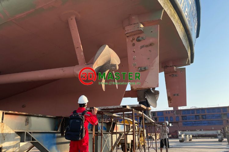
Depending on component geometry, inspection locations, and required tolerances, businesses can choose 3D scanning, CMM measurement, or a combination of both to assess the condition of shaft systems and propellers after prolonged operation.
Inspection using a laser 3D scanner: Captures high-density surface data, reconstructs a 3D model, and identifies deviation areas by comparing the results with reference data.
Inspection using a CMM machine: Uses a probe to determine coordinates, dimensions, and critical geometric characteristics such as circularity, cylindricity, and positional relationships.
Combined 3D scanning and CMM inspection: Uses 3D scanning to assess the overall surface, followed by CMM measurements to verify critical dimensions and tolerances according to technical requirements.
Inspection and comparison of 3D data before and after repair: Compares measurement data with the CAD model or reference measurements to evaluate geometric restoration and support acceptance inspection.
Note: 3D scanning and CMM do not directly identify the causes of wear. Accurate wear assessment requires appropriate reference data and a measurement method capable of meeting the specified tolerance requirements.
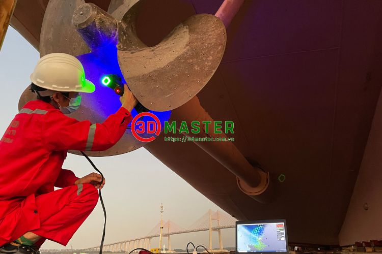
To ensure reliable assessment results for classification surveys and repairs, the 3D inspection process typically follows six standardized steps:
Step 1: Assess the component and define measurement requirements: Receive the shaft assembly, clean the surfaces to remove grease, marine growth, and rust, and identify applicable technical standards and allowable tolerances based on the manufacturer's drawings or classification society rules.
Step 2: Capture geometric data: Set up the 3D scanner or CMM machine and scan or measure the propeller shaft assembly from multiple angles to capture the required geometry, including areas that are difficult to access.
Step 3: Process the measurement data: Convert point cloud data into a triangular polygon mesh, remove noise, and optimize the 3D model representing the shaft assembly after operation.
Step 4: Compare against reference data: Align the actual 3D model with the original design CAD model or baseline measurement data using an appropriate coordinate reference system.
Step 5: Analyze results and prepare a report: Generate a detailed report containing color deviation maps, wear measurements at individual locations, shaft runout measurements, and specific technical recommendations.
Step 6: Perform post-repair inspection: Rescan and inspect the shaft assembly after machining, weld build-up restoration, or dynamic balancing to verify compliance with applicable requirements before reinstalling it on the vessel.
Inspecting large mechanical components such as marine shaft assemblies requires technicians to understand key measurement principles to avoid errors:
Establish the correct reference for comparison: Use the reference coordinate system defined in the design drawings when aligning data to prevent errors caused by shaft movement during scanning.
Select the appropriate method based on tolerances: Clearly distinguish between areas requiring overall surface assessment using a 3D scanner and areas requiring strict inspection of assembly tolerances using CMM.
Distinguish geometric deviations from wear: Understand the causes of deformation, such as residual stress, impact, and temperature, to differentiate them from material loss caused purely by operational friction.
Comply with safety and inspection requirements: Ensure measurement equipment is calibrated periodically and maintain a stable measurement temperature to minimize the effects of metal thermal expansion.


3D Master is proud to provide industrial 3D scanning, 3D inspection, and quality inspection solutions for large mechanical components in Vietnam.
With advanced portable inspection equipment, modern CMM systems, and an experienced engineering team with practical expertise in shipbuilding and heavy industry, 3D Master delivers comprehensive 3D inspection solutions:
On-site inspection at docks and workshops: Portable laser 3D scanners support the measurement of oversized shaft assemblies and propellers without requiring transportation to another facility.
Classification inspection reports: Generate clear 3D deviation reports using color maps, with measurement accuracy potentially reaching the micrometer level depending on the equipment and inspection conditions, to support classification surveys and acceptance procedures.
Integrated solutions: 3D digitization, reverse engineering to reconstruct CAD drawings, and post-machining restoration inspection support.
For large, complex mechanical components such as marine propeller shafts and propellers, selecting suitable measurement equipment is essential to improving inspection and repair efficiency.
In summary, 3D inspection of marine propeller shaft wear helps businesses assess component conditions more accurately, detect geometric deviations, and control quality after repairs. Combining 3D scanning with coordinate measuring machines (CMMs) enables more comprehensive inspection, depending on component characteristics and tolerance requirements. If your business needs to digitize components, analyze deviations, or reconstruct geometric data for complex mechanical parts, 3D Master is ready to recommend suitable 3D scanning solutions to optimize inspection processes and improve maintenance and repair efficiency.
3D Master Contact Information:
Hotline / Zalo / Telegram / WhatsApp / LINE / Viber / KakaoTalk: +84 982 089 198 | 0986333960
Email: cuong3dmaster@gmail.com | hung3dmaster@gmail.com | tech3dmaster@gmail.com
Website: https://3dmaster.com.vn