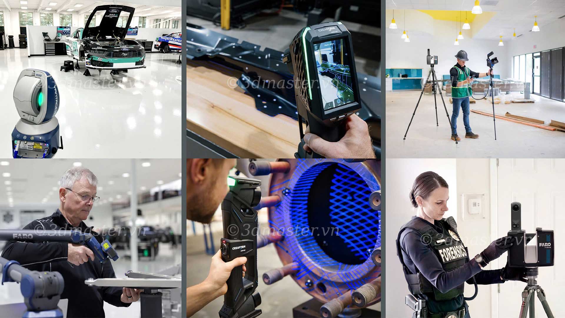
Digitizing aerospace components using traditional measurement methods is extremely time-consuming because aerodynamic structures contain numerous freeform curved surfaces. Measuring individual points manually is not only slow but also increases the risk of overlooking actual deformations. To improve efficiency, modern workflows apply 3D scanning technology to rapidly capture geometric data, providing an accurate foundation for creating fighter aircraft drawings in CAD software. This solution also supports the development of military aircraft drawings, covering everything from fighter jet components to research projects involving Vietnamese fighter aircraft drawings and helicopter drawings.
.jpg)
In aircraft manufacturing and maintenance, fighter aircraft drawings are critical technical documents that determine the precision and safety of aircraft systems and equipment.
Accurate representation of shape, dimensions, and structure: Provides precise geometric specifications, aerodynamic profiles, and allowable tolerances for individual components.
A foundation for design, manufacturing, assembly, and maintenance: Defines CNC machining processes, workpiece positioning, quality inspection, and maintenance, repair, and overhaul (MRO) planning.
A 3D CAD foundation for complex components: Supports aerodynamic flow simulation, structural strength calculations using finite element analysis (FEA), and collision analysis.
However, fighter aircraft drawings and CAD data are not always available, particularly for aircraft that have been in service for many years or components that have deformed during operation.
This is where 3D scanning technology comes into play, enabling engineers to reconstruct the required input data quickly and accurately.
One point must be made clear: 3D scanning does not replace the engineering judgment of design engineers. Instead, it serves as a powerful productivity tool, significantly shortening the initial geometric data acquisition and reconstruction stages compared with manual measurement or building a 3D aircraft model from scratch.
With traditional measurement methods, engineers typically select individual measurement points, position measuring instruments at the required locations, and record dimensions. As the number of points increases, the time required for measurement and data compilation also increases.
3D scanning works differently. A scanner can capture a large number of points across a surface during each scan, generating a 3D point cloud that represents the actual geometry of the component.
This helps to:
Reduce the number of manual measurement operations.
Capture data across large surface areas quickly.
Minimize the risk of overlooking geometric features.
Generate input data directly for 3D processing.
In aerospace applications, optical and laser scanning technologies are used to capture data at high speeds for both inspection and reverse engineering.
.jpg)
A dimensional table provides only the information selected for measurement in advance. In contrast, scan data can capture component surface geometry across a much broader area.
The point cloud can be processed into a 3D mesh, allowing engineers to visually inspect:
Curves and profiles.
Freeform surfaces.
Holes and grooves.
Edges and boundaries.
Relative positions between different regions.
Areas exhibiting deformation or deviation.
For components with complex geometries, having comprehensive 3D data significantly reduces the need for additional measurements caused by missing information during CAD modeling.
Comprehensive 3D data can also help identify dents, gaps, wrinkles, and surface deviations during maintenance, repair, and overhaul (MRO).

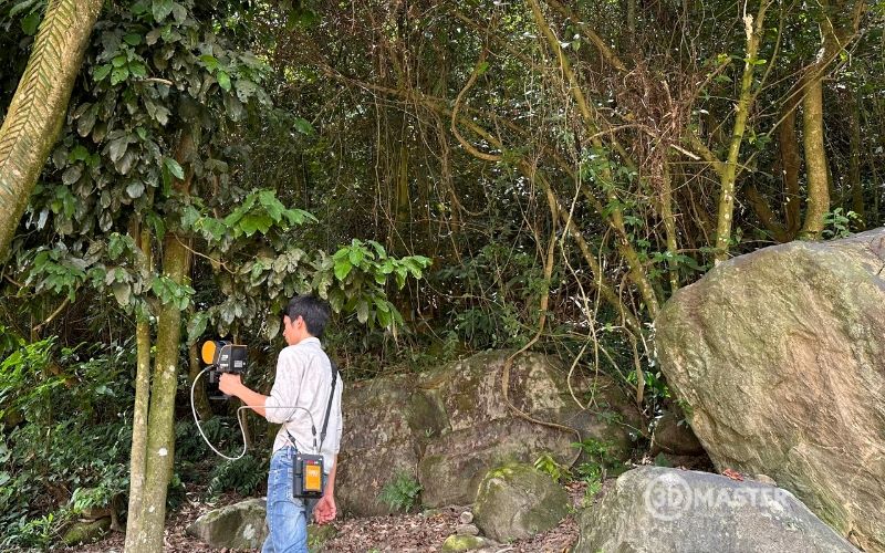
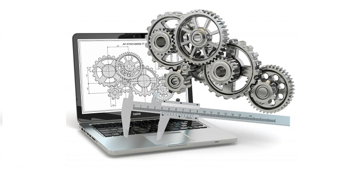
One of the main reasons manual measurement processes take so long is the need to repeat several stages: Measure → Model → Identify missing data → Take additional measurements → Revise → Reinspect.
With 3D scanning, geometric data is stored digitally. If engineers need to verify an additional dimension or revisit a scanned area, much of the required information can be retrieved directly from the 3D data without positioning measuring instruments on the component again.
This is particularly useful for components that are difficult to access or have numerous complex surfaces.
Modern 3D measurement systems can also capture large areas with fewer measurement operations, thereby reducing inspection and processing time.
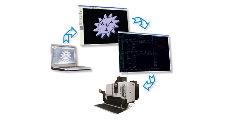
After scanning, the resulting data does not immediately constitute a complete fighter aircraft design. The point cloud or mesh must be processed and analyzed to identify the geometric features required for the CAD model.
The workflow may follow this sequence:
Point Cloud → Mesh → Geometric Analysis → Reverse Engineering → CAD
Specialized software can help engineers identify planes, circles, profiles, curved surfaces, and other geometric features from scan data. Engineers can then reconstruct the CAD model and analyze deviations between the model and the original scan data.
Therefore, when the appropriate equipment, software, and workflow are used, substantial time savings are technically achievable. Some projects may target a reduction of up to 70% compared with the corresponding manual measurement and modeling workflow.
To convert a complex mechanical component into a technically accurate 3D fighter aircraft drawing, the process involves six standard steps:
Step 1: Component assessment: Evaluate the component's dimensions, material, surface finish, and critical profiles that need to be captured.
Step 2: 3D scanning: Use specialized 3D scanning equipment, such as laser scanners or handheld scanners, to capture the component's spatial geometry.
Step 3: Data processing: Clean the point cloud, align scans from different angles, and convert the data into a 3D mesh.
Step 4: Reverse engineering: Extract geometric features and accurately reconstruct parametric curved surfaces based on the mesh data.
Step 5: CAD modeling and drawing generation: Refine the complete 3D solid model and export 2D or 3D fighter aircraft drawings for machining and manufacturing.
Step 6: Verification: Compare the completed CAD model with the original 3D scan data to ensure that accuracy remains within the permitted tolerance.
.jpg)
3D scanning is particularly effective when component design and restoration processes encounter the following challenges:
When original drawings or CAD files are unavailable: Suitable for older military aircraft and imported components whose technical documentation has been lost.
When existing drawings no longer reflect actual conditions: Components may have deformed, worn down, or undergone multiple rounds of manual repairs after years of service.
When components have complex geometries: Propeller blades, aerodynamic housings, and engine components may feature intricate 3D curved profiles that are difficult to measure using conventional methods.
When deviation inspection is required: Assess component warpage and wear after a specified number of flight hours.
When components need to be redesigned: Modify structures, optimize weight, or change machining materials to suit domestic manufacturing capabilities.
Beyond producing fighter aircraft drawings, 3D digitization provides a foundation for many modern engineering activities:
Aircraft component digitization: Build comprehensive digital databases of spare parts and components for long-term storage.
Component reverse engineering: Accurately reconstruct parts to support domestic manufacturing.
Dimensional inspection and deviation analysis: Compare newly machined components or repaired parts against reference design drawings.
MRO support: Accelerate aircraft maintenance, repair, and overhaul workflows.
Digital CAD library development: Store 3D models in cloud-based systems for retrieval and use in 3D printing or automated machining when required.
Replacement component manufacturing: Rapidly produce individual spare parts that are no longer supplied by the original manufacturer.
Helicopter component digitization: Apply 3D scanning to rotor systems, gearboxes, and helicopter fuselages.
UAV and drone component digitization: Optimize the design and manufacturing processes for unmanned aircraft.
Beyond complex industrial applications, accurate 3D scan data also supports the development of realistic simulation models, making structural research more accessible. This is fundamentally different from conventional artistic modeling activities, such as simple fighter aircraft drawing, helicopter drawing, or learning the easiest way to draw an aircraft on paper.
With advanced equipment and an experienced engineering team, 3D Master provides high-accuracy 3D scanning, reverse engineering, and 3D measurement solutions for aerospace manufacturing and maintenance. The company delivers accurate CAD data, helping businesses and technical organizations reduce fighter aircraft CAD modeling time by up to 70% and digitize complex components.
>>> Explore professional 3D scanning and aerospace component digitization services now.
Contact 3D Master:
Hotline / Zalo / LINE / Telegram / WhatsApp / Viber / KakaoTalk: +84 982 089 198 | 0986333960
Email: cuong3dmaster@gmail.com | hung3dmaster@gmail.com | tech3dmaster@gmail.com
Website: https://3dmaster.com.vn