3D Scanning Helps the Machinery Manufacturing Industry Reduce Scrap Caused by Warping
3D Scanning Helps the Machinery Manufacturing Industry Reduce Scrap Caused by Warping
Posted Date: 20-11-2026
3D Scanning Helps the Machinery Manufacturing Industry Reduce Scrap Caused by Warping
In the machinery manufacturing industry, parts can warp after CNC machining or heat treatment. This can cause dimensional deviations, affect fit during assembly, and increase production costs. So what is machinery manufacturing technology, and how can manufacturers assess deformation that is difficult to detect with conventional inspection methods? 3D scanning technology captures surface geometry, identifies areas of deviation, and helps engineers assess whether a part can be corrected. This can reduce scrap and improve manufacturing efficiency.
1. What is machinery manufacturing technology?
Machinery manufacturing technology is an engineering field that develops and applies methods for designing, machining, manufacturing, assembling, and inspecting machine parts, mechanical equipment, and machinery systems for industrial production.
It draws on mechanics, materials science, machining technology, control systems, and automation to produce components and equipment that meet requirements for accuracy, durability, and performance.
In practice, the machinery manufacturing industry uses technologies such as CNC machining, CAD/CAM, coordinate measuring machine (CMM) inspection, and 3D scanning to improve quality control.
3D scanning captures the actual geometry of machined parts so engineers can compare them with the design and identify deformation that could affect product quality.
Warping after machining affects part accuracy and fit during assembly.
2. What is part warping, and why do machine parts warp after machining or heat treatment?
Warping occurs when a machine part changes shape relative to its design geometry or a reference condition. It can appear as bowing, out-of-plane distortion, twisting, or localized deformation.
Warping can occur during machining, after a part is removed from its fixture, or during heat treatment.
In the machinery manufacturing industry, warping is influenced by machine accuracy, the stress distribution within the part, material properties, and processing conditions.
Release of residual stress. Removing material redistributes internal stresses in the workpiece, which can cause the part to bow or twist.
Cutting forces and machining heat. Cutting forces, plastic deformation, and heat generated during machining can induce residual stresses and distort the part.
Improper clamping force. Excessive or uneven clamping can deform the part and cause geometric deviations once it is released from the fixture.
Uneven heating or cooling. Temperature differences cause uneven expansion and contraction, which can lead to warping.
Changes in material microstructure. Phase transformations and associated volume changes during heat treatment can deform the part.
Part design and machining sequence. Thin walls, asymmetric geometry, or an unsuitable cutting sequence can increase the risk of warping.
Warping can also cause a part to fall outside geometric tolerances, shift mating features out of position, complicate assembly, or prevent the part from meeting operating requirements.
Manufacturers may need to add straightening or corrective machining operations. Parts may have to be scrapped if the deformation cannot be corrected. This increases scrap rates, wastes material, and delays production.
3. Why do conventional inspection methods struggle to assess warped parts?
In the machinery manufacturing industry, calipers, micrometers, dial indicators, and other contact measuring devices remain important for checking dimensions and tolerances.
When engineers need to determine how deformation is distributed across a complex part, manual measurements taken at individual locations have several limitations.
Limited coverage of the overall deformation. Handheld instruments measure selected locations, making it difficult to assess an entire curved surface or a part with complex geometry.
Difficulty locating the most distorted areas. Deviations can vary across a part. Measuring only a few locations can miss localized deformation or areas with large deviations.
Difficulty comparing the entire part with CAD. Isolated measurements make it difficult to compare the actual shape with the design, especially on surfaces with complex profiles.
These limitations can make warping assessment time-consuming, particularly when engineers need to determine the extent of deformation before deciding how to repair a part.
3D scanning provides additional surface geometry data alongside conventional measurement methods and CMM inspection.
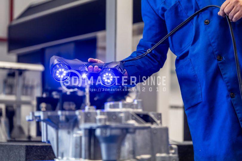
3D scanning captures the actual shape of a machine part after machining.
4. How does 3D scanning help the machinery manufacturing industry inspect and analyze warping?
In the machinery manufacturing industry, 3D scanning captures dense surface measurements to help engineers assess part deformation after machining or heat treatment.
When used with dedicated inspection software, it allows engineers to visualize deviations, quantify warping, and use the measurements to select a suitable corrective action.
The process includes the following steps.
Digitize the actual shape. A 3D scanner captures the part’s surface after machining and produces a 3D representation of its actual shape.
Compare the scan with the CAD model. Engineers align the scan data with the design model and use a color deviation map to identify where the part has deformed and in which direction.
Assess the extent of warping. Engineers compare the magnitude and extent of deviations and the affected geometric features with the design tolerances.
Evaluate corrective options. Inspection data helps determine whether the part can be straightened or corrected through machining, or whether it needs to be remanufactured.
Inspect the part after correction. Engineers rescan the part and compare the results with both the CAD model and the initial scan to verify the effectiveness of the correction and support acceptance inspection.
5. Applications of 3D scanning for warping control at different stages of machinery manufacturing
Using 3D scanning at appropriate inspection points helps engineers track geometric changes, locate deviations, and assess part quality.
Inspect for warping after CNC machining. Scan the part after removing it from the fixture to identify profile and flatness deviations and help determine how it can be corrected through machining.
Assess deformation after heat treatment. Compare the part’s geometry before and after heat treatment to identify areas where deformation affects accuracy or fit during assembly.
Inspect cast parts and metal structures. Compare 3D scan data with the CAD model to detect deviations caused by shrinkage or uneven cooling and assess machining allowance.
Check quality after straightening or corrective machining. Reinspect the part against the design tolerances and verify the effectiveness of the correction before moving it to the next operation.
For parts with tight tolerances, 3D scan data can be combined with CMM measurements or other specialized inspection methods to provide a more complete assessment.
6. How 3D scanning helps machinery manufacturers reduce losses caused by warping
In the machinery manufacturing industry, controlling warping helps manufacturers reduce scrap, save material, and improve production quality.
When applied according to the part’s technical requirements, 3D scanning offers several practical benefits.
Detect deviations early and limit rework. Identifying deformed areas before assembly helps manufacturers assess whether a part can be salvaged through targeted correction.
Improve quality inspection. Color deviation maps and inspection reports make it easier to compare the part’s actual shape with the CAD design.
Improve manufacturing processes and reduce recurring warping. Deformation data can inform changes to fixturing, machining sequences, and heat treatment.
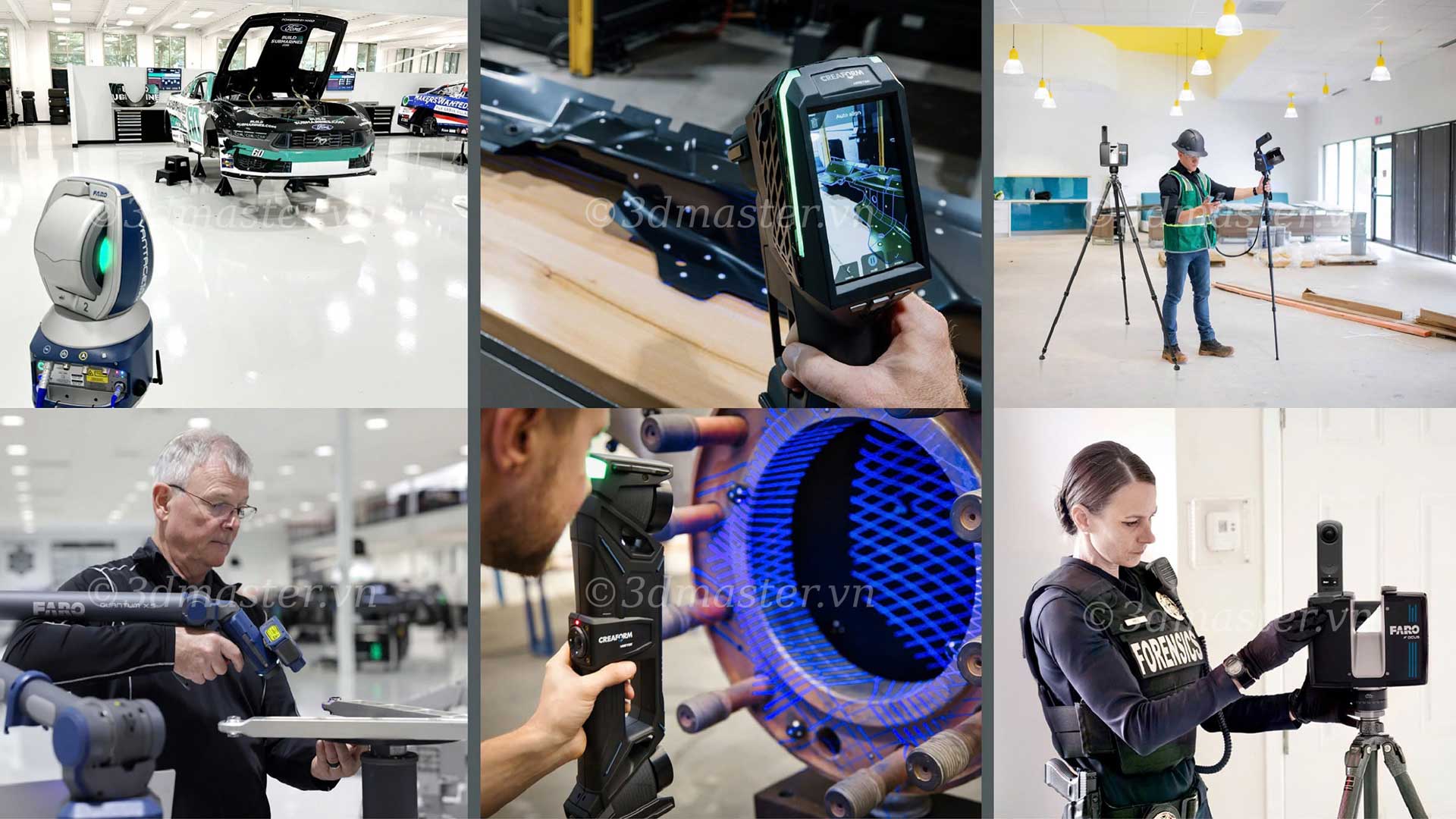
Select a suitable 3D scanning solution. The part’s size, material, geometric complexity, and tolerances guide the choice of scanning equipment and inspection methods.
3D Master provides industrial 3D digitization solutions to companies in the machinery manufacturing industry. Its services include digitizing parts and collecting geometric data for inspection and deviation analysis according to each project’s technical requirements.
3D scan data helps manufacturers establish the extent of deformation before deciding whether to repair, rework, or scrap a part.
Warping after machining and heat treatment is a significant challenge in the machinery manufacturing industry. It affects part accuracy, fit during assembly, and production efficiency. With 3D scanning, engineers can capture surface geometry, visualize deviations, and assess the extent of deformation before choosing a corrective action. This helps manufacturers improve part quality, reduce scrap, and refine their production processes over time.
>>> Cut inspection time and control costs with 3D Scanning Services. Get started today!